Magnetic absorption separated lifting camera

A magnetic adsorption and separation technology, applied in the direction of non-rotational vibration suppression, friction transmission, belt/chain/gear, etc., can solve the problem of poor stability and reliability of lifting cameras, limit the application and development of lifting cameras, transmission parts or guides Problems such as component breakage can be eliminated, and the process yield and mass production capacity are high, the structure is simple, and the service life is long.

Inactive Publication Date: 2019-08-02
LEADING TECH DONGTAI CO LTD
View PDF0 Cites 6 Cited by
  • Summary
  • Abstract
  • Description
  • Claims
  • Application Information

AI Technical Summary

Problems solved by technology

However, because the technology of integrated camera under the screen is far from mature, the camera cannot penetrate the display screen to take pictures, so the front camera must be designed in an area other than the display screen. In order to achieve a full screen, the camera is often hidden on the back of the display screen. When taking pictures, the camera is extended, that is, it is designed as a camera that can be lifted. As an effective way to realize a full screen, the technology of lifting the camera has formed a new wave in recent years.
[0003] In the prior art, the lifting camera mainly includes manual pressing pop-up type, manual rotating type, and variable speed motor automatic type, etc., but there are certain defects in the design of the existing lifting camera. The camera module and the transmission guide mechanism are often rigidly connected. When the camera When the module is impacted, the impact force will all act on the transmission and guide mechanism, which may cause irreversible damage such as breakage of the transmission or guide, resulting in poor stability and reliability and low life of the lifting camera, which limits Application and Development of Elevating Camera

Method used


Image

  • Magnetic absorption separated lifting camera
  • Magnetic absorption separated lifting camera
  • Magnetic absorption separated lifting camera

Examples


Embodiment

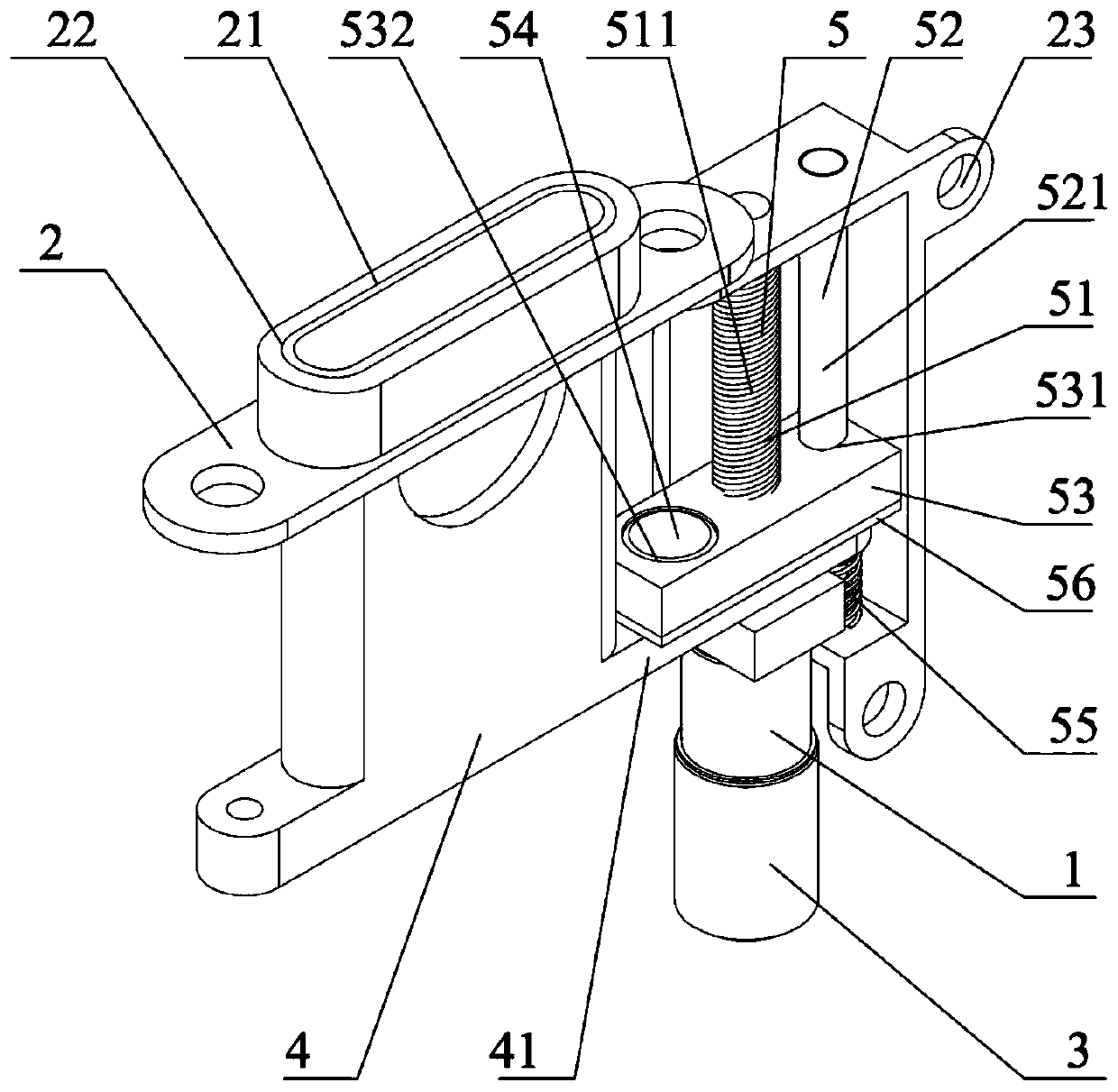
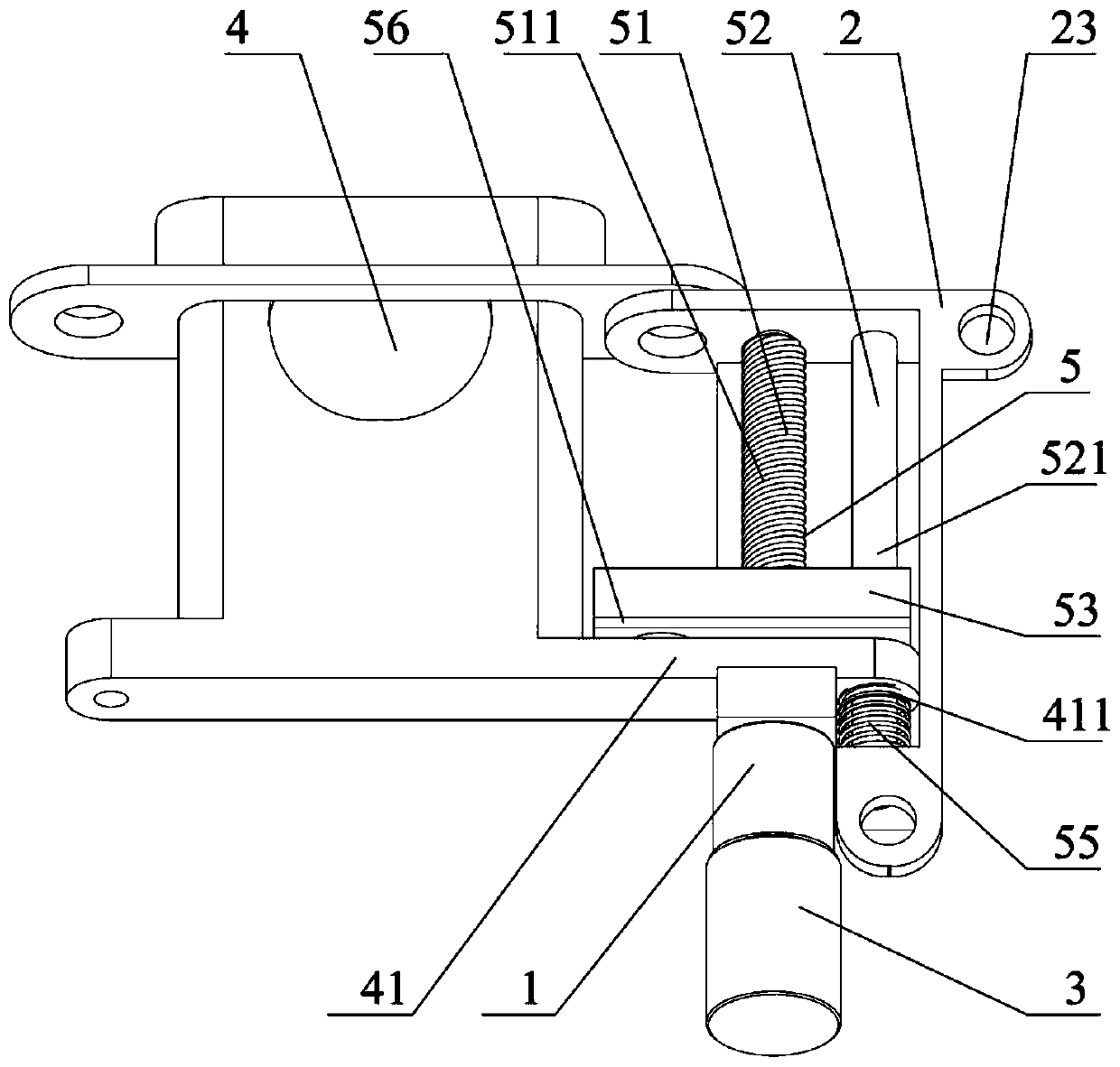
[0027] A magnetic adsorption detachable lifting camera, such as Figure 1~6 As shown, it includes a support frame 2 and a motor 3. The support frame 2 is provided with a camera module 4 and a lifting assembly 5 that drives the camera module 4 to lift. The moving block 53 and the guide mechanism 52 matched with the moving block 53, the camera module 4 has a first extension 41, the moving block 53 is magnetically attached to the first extension 41 through a permanent magnet 54, that is, the camera module 4 The first protruding part 41 and the moving block 53 can realize detachable connection, the first protruding part 41 is slidably connected with the guide mechanism 52, and the lower end of the guide mechanism 52 is provided with a first protruding part for separating from the moving block 53. The elastic element 55 matched with the part 41, the elastic element 55 is usually located at the initial position of the first protruding part 41, and the output end of the motor 3 is co...


PUM


Abstract

The invention discloses a magnetic absorption separated lifting camera. The magnetic absorption separated lifting camera comprises a support frame and a motor; the support frame is provided with a camera module and a lifting module for driving the camera module to lift; the lifting module comprises a lead screw mechanism, a movable block arranged on the lead screw mechanism, and a guide mechanismmatched with the movable block; the camera module is provided with a first extension part; the movable block is in magnetic absorption connection with the first extension part through a permanent magnet; an elastic element for matching with the first extension part after separation from the movable block is arranged at the lower end of the guide mechanism; and an output end of the motor is connected with the lead screw mechanism. The magnetic absorption separated lifting camera realizes separated connection between the camera module and the lifting module; and the elastic element can achieve abuffer protecting effect to prevent direct acting of impact force on a transmission component, so that the damage of the transmission component is effectively reduced, the impact resistance, the stability and the reliability of products are improved, the service life is longer, and the progress yield and the mass production capacity are higher.

Description

technical field [0001] The invention relates to the technical field of mechanical transmission, in particular to a magnetic adsorption detachable lifting camera. Background technique [0002] With the rapid development of science and technology, 3C electronic products have been widely used in people's work and life, especially in mobile terminal electronic devices such as mobile phones and tablet computers. 3C electronic products are computers, communications and consumer electronics products. (Consumer Electronic) The abbreviation of the three types of electronic products. In order to cater to people's consumption experience, high screen-to-body ratio or full-screen technology has become the main development trend of these electronic devices. The high screen-to-body ratio or full-screen technology has outstanding advantages such as atmosphere and beauty, which are very in line with people's consumption experience. The screen requirements of electronic devices are also gett...

Claims


Application Information

Patent Timeline
Patent Type & Authority Applications(China)
IPC IPC(8): F16M11/04F16M11/18F16H19/02F16F15/08
CPCF16F15/08F16H19/02F16M11/046F16M11/18
Inventor 李志锋王磊张良威
Owner LEADING TECH DONGTAI CO LTD
Why Eureka
Try Eureka