A binocular point cloud generation method and system

A point cloud generation, binocular technology, applied in image analysis, image enhancement, instruments and other directions, can solve problems such as high noise, large deviation of point cloud generation, and fisheye cameras cannot be well implemented.

Active Publication Date: 2020-12-04
ECARX (HUBEI) TECHCO LTD
View PDF11 Cites 0 Cited by
  • Summary
  • Abstract
  • Description
  • Claims
  • Application Information

AI Technical Summary

Problems solved by technology

Using the currently commonly used machine learning method to detect static obstacles needs to know the type of obstacle and a large amount of training data in advance. This method makes the versatility and flexibility of finding parking spaces poor.
[0003] In addition, the latest research hotspot at present is to use point cloud to realize static obstacle detection, but usually need to use better global camera (Global Shutter Camera), or binocular camera, and the fisheye camera equipped on a large number of existing cars can't be achieved well
The existing visual SLAM (Simultaneous Localization And Mapping) point cloud generation method based on a monocular fisheye camera mainly has problems such as poor stability, low precision, and difficulty in obtaining the true scale of static obstacles.
Among them, the poor stability is mainly manifested in the frequent initialization failures in the point cloud generation process, the large deviation of point cloud generation, the large noise, and the large scale deviation of the point cloud that can be generated.

Method used


Image

  • A binocular point cloud generation method and system
  • A binocular point cloud generation method and system
  • A binocular point cloud generation method and system

Examples


Embodiment Construction

[0039] Exemplary embodiments of the present disclosure will be described in more detail below with reference to the accompanying drawings. Although exemplary embodiments of the present disclosure are shown in the drawings, it should be understood that the present disclosure may be embodied in various forms and should not be limited by the embodiments set forth herein. Rather, these embodiments are provided for more thorough understanding of the present disclosure and to fully convey the scope of the present disclosure to those skilled in the art.

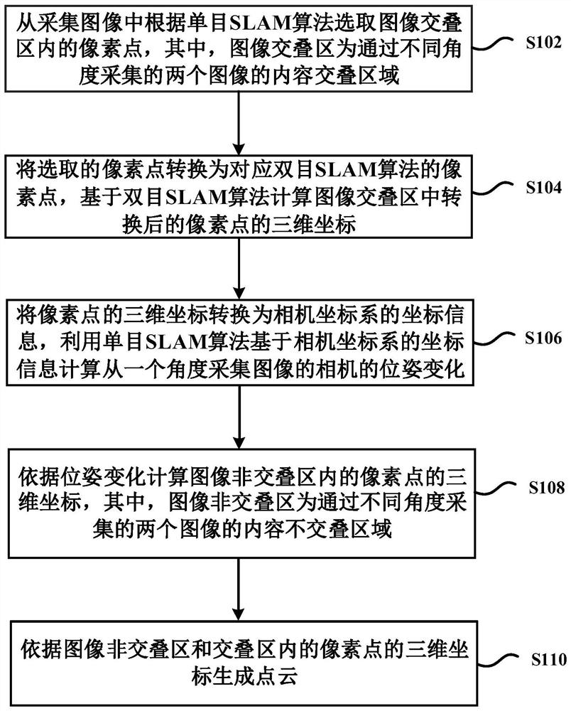
[0040] In order to solve the above technical problems, an embodiment of the present invention provides a binocular point cloud generation method, figure 1 A schematic flowchart of a method for generating a binocular point cloud according to an embodiment of the present invention is shown. see figure 1 , the method at least includes step S102 to step S110.

[0041] Step S102, selecting pixels in the image overlapping area from the...


PUM


Abstract

The present invention provides a method and system for generating a binocular point cloud, the method comprising: selecting pixels in the image overlapping area from the collected image according to the monocular SLAM algorithm, and converting the selected pixel points into corresponding binocular SLAM algorithms After the pixel point is calculated, the three-dimensional coordinates of the converted pixel point in the image overlap area are calculated based on the binocular SLAM algorithm, and the three-dimensional coordinates of the pixel point are converted into the coordinate information of the camera coordinate system, and the monocular SLAM algorithm is used based on the camera coordinate system The three-dimensional coordinates of the pixels in the non-overlapping area of ​​the image are calculated from the coordinate information of the image, and the point cloud is generated according to the three-dimensional coordinates of the pixels in the non-overlapping area and the overlapping area of ​​the image. The scheme of the present invention calculates the scale according to the pixel point information in the image overlapping area of ​​the collected image, and obtains the pixel point information in the non-overlapping area of ​​the image. The binocular SLAM algorithm is used to assist the monocular SLAM algorithm to obtain mature points in the image faster and more accurately, which improves the stability of point cloud generation and the accuracy of object real scale acquisition.

Description

technical field [0001] The invention relates to the technical field of automobiles, in particular to a binocular point cloud generation method and system. Background technique [0002] At present, in the automatic parking assistance system (Auto Parking Assist, APA) solution, there are generally 4 low-cost fisheye cameras, which are used to realize the function of the Around View Monitoring (AVM) system, or to achieve the same APA-related visual display effects. In the prior art, when a vehicle uses APA to find a parking space, it usually needs to detect parking spaces and static obstacles, such as ice cream cones, wheel chocks, poles and net fences, etc., and even some uncommon obstacles, such as bicycles, chairs and more. Using the currently commonly used machine learning method to detect static obstacles needs to know the type of obstacles and a large amount of training data in advance, which makes the generality and flexibility of finding parking spaces poor. [0003]...

Claims


Application Information

Patent Timeline
Patent Type & Authority Patents(China)
IPC IPC(8): G06T7/73G06T7/80
CPCG06T2207/10028G06T7/74G06T7/80
Inventor 杨文龙P·尼古拉斯
Owner ECARX (HUBEI) TECHCO LTD
Why Eureka
Try Eureka