Visual positioning method and system

A visual positioning and visual technology, applied in the field of visual positioning, can solve the problems of large volume of laser sensors, inability to expand and develop functions, and limit visual positioning systems, etc., to achieve rich visual texture images and visual geometric information, easy deployment and operation, The effect of expanding the scope of application

Inactive Publication Date: 2019-08-02
北京易达图灵科技有限公司
View PDF8 Cites 10 Cited by
  • Summary
  • Abstract
  • Description
  • Claims
  • Application Information

AI Technical Summary

Problems solved by technology

[0003] However, there are many defects in the laser sensor itself, which limit the application of the visual positioning system. For example, the laser sensor is generally large in size, which makes it impossible to install and deploy in many application scenarios, which limits the large-scale applicati

Method used


Image

  • Visual positioning method and system
  • Visual positioning method and system
  • Visual positioning method and system

Examples


Embodiment Construction

[0021] In order to make the purpose, technical solutions and advantages of the embodiments of the present invention clearer, the technical solutions in the embodiments of the present invention will be clearly and completely described below in conjunction with the drawings in the embodiments of the present invention. Obviously, the described embodiments It is a part of embodiments of the present invention, but not all embodiments. Based on the embodiments of the present invention, all other embodiments obtained by persons of ordinary skill in the art without creative efforts fall within the protection scope of the present invention.

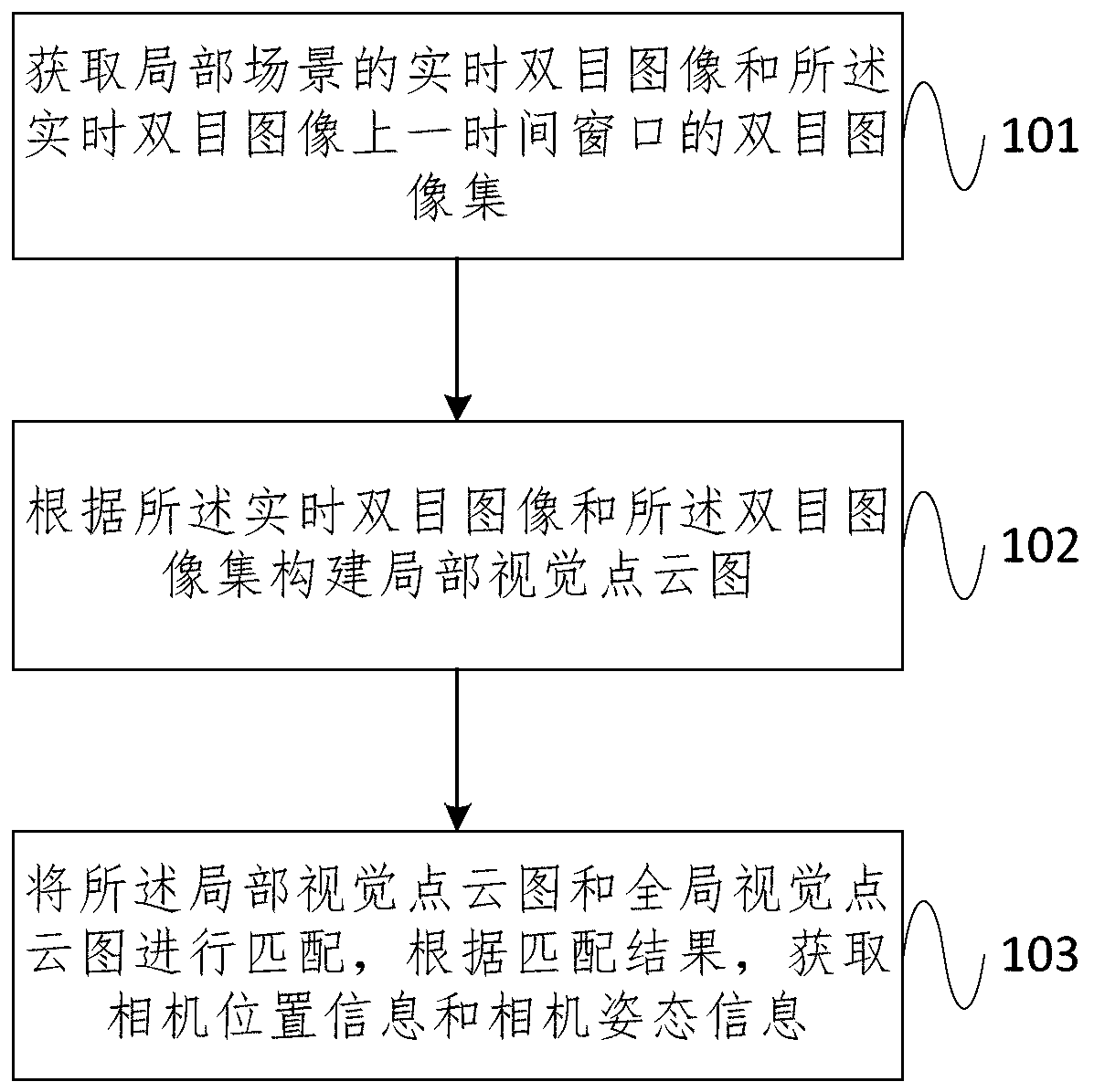
[0022] The laser is used as a sensor to obtain 3D point cloud data and realize the positioning in the known 3D point cloud map. The core is to use the local real-time point cloud of the laser sensor to match the global 3D point cloud map. However, the laser sensor itself has many defects, which limit the application of the visual positioning syste...


PUM


Abstract

The embodiment of the invention provides a visual positioning method and system. The visual positioning method comprises the steps of obtaining a real-time binocular image of a local scene and a binocular image set of a previous time window of the real-time binocular image; constructing a local visual point cloud picture according to the real-time binocular image and the binocular image set; and matching the local visual point cloud picture with the global visual point cloud picture, and obtaining camera position information and camera attitude information according to a matching result. According to the embodiment of the invention, the real-time binocular image is acquired through the binocular vision camera; a local visual point cloud picture is constructed according to the real-time binocular image and the binocular image in the previous time sequence. According to the embodiment of the invention, deployment and operation are easier, the visual positioning efficiency is improved, meanwhile, more abundant visual texture images and visual geometric information are provided, and the application range of visual positioning is expanded.

Description

technical field [0001] Embodiments of the present invention relate to the technical field of visual positioning, and in particular, to a visual positioning method and system. Background technique [0002] In the existing visual positioning technology, the laser is used as a sensor to obtain 3D point cloud data, and the positioning in the known 3D point cloud map is realized. [0003] However, there are many defects in the laser sensor itself, which limit the application of the visual positioning system. For example, the laser sensor is generally large in size, which makes it impossible to install and deploy in many application scenarios, which limits the large-scale application of the visual positioning system. . In addition, the laser sensor itself acquires spatial point cloud data. The information contained in these data is not rich enough, and it is difficult to use it for other purposes except for positioning, so more function expansion and development cannot be carried...

Claims


Application Information

Patent Timeline
IPC IPC(8): G06T7/73G06T7/33G01C21/00G01B11/00
CPCG01B11/00G01C21/00G06T7/33G06T7/73G06T2207/10028
Inventor 刘洋华仁红王毓玮
Owner 北京易达图灵科技有限公司
Why Eureka
Try Eureka