
Display panel

A display panel and display area technology, applied in photovoltaic power generation, electrical components, circuits, etc., can solve the problems of poor light output rate, thick panel thickness, unfavorable camera module performance, etc., to improve light transmittance and camera performance. , easy to bend

Active Publication Date: 2019-08-02
WUHAN CHINA STAR OPTOELECTRONICS SEMICON DISPLAY TECH CO LTD
View PDF4 Cites 25 Cited by
  • Summary
  • Abstract
  • Description
  • Claims
  • Application Information

AI Technical Summary

Problems solved by technology

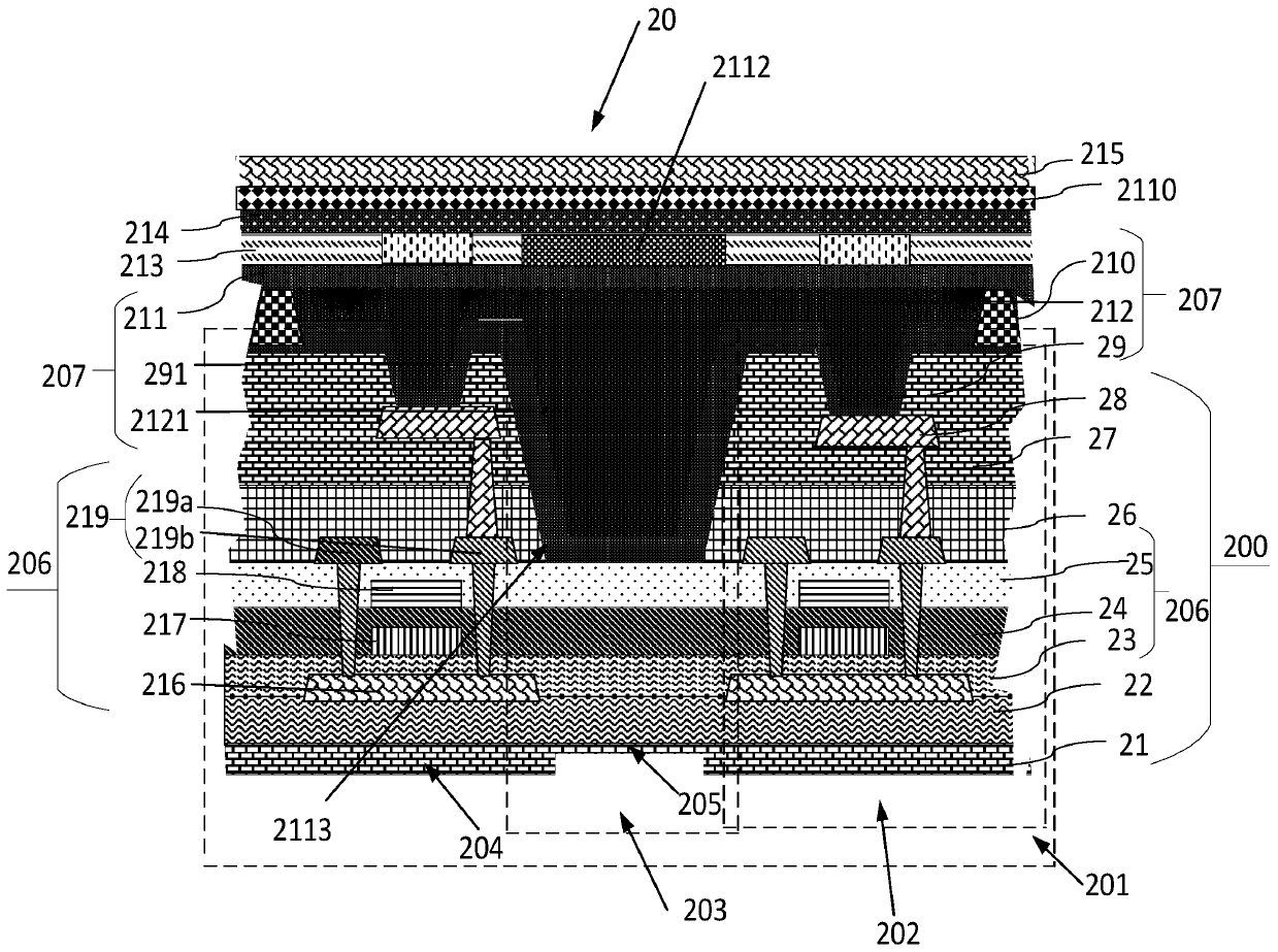
[0005] The purpose of the present invention is to provide a display panel, which can effectively solve the problems of thick panel, poor light output rate, unfavorable camera module performance, etc.

Method used


Image

  • Display panel
  • Display panel

Examples


Embodiment Construction

[0034] The following description of the various embodiments refers to the accompanying drawings to illustrate specific embodiments in which the present invention may be used. The directional terms mentioned in the present invention, such as up, down, front, rear, left, right, inner, outer, side, etc., are only referring to the directions of the drawings. The names of the components mentioned in the present invention, such as the first, the second, etc., are only to distinguish different components and can be better expressed. In the figures, structurally similar elements are denoted by the same reference numerals.

[0035] Embodiments of the present invention will be described in detail herein with reference to the accompanying drawings. The present invention may be embodied in many different forms and should not be construed solely as the specific embodiments set forth herein. The present invention provides these embodiments in order to explain the practical application of ...


PUM


Abstract

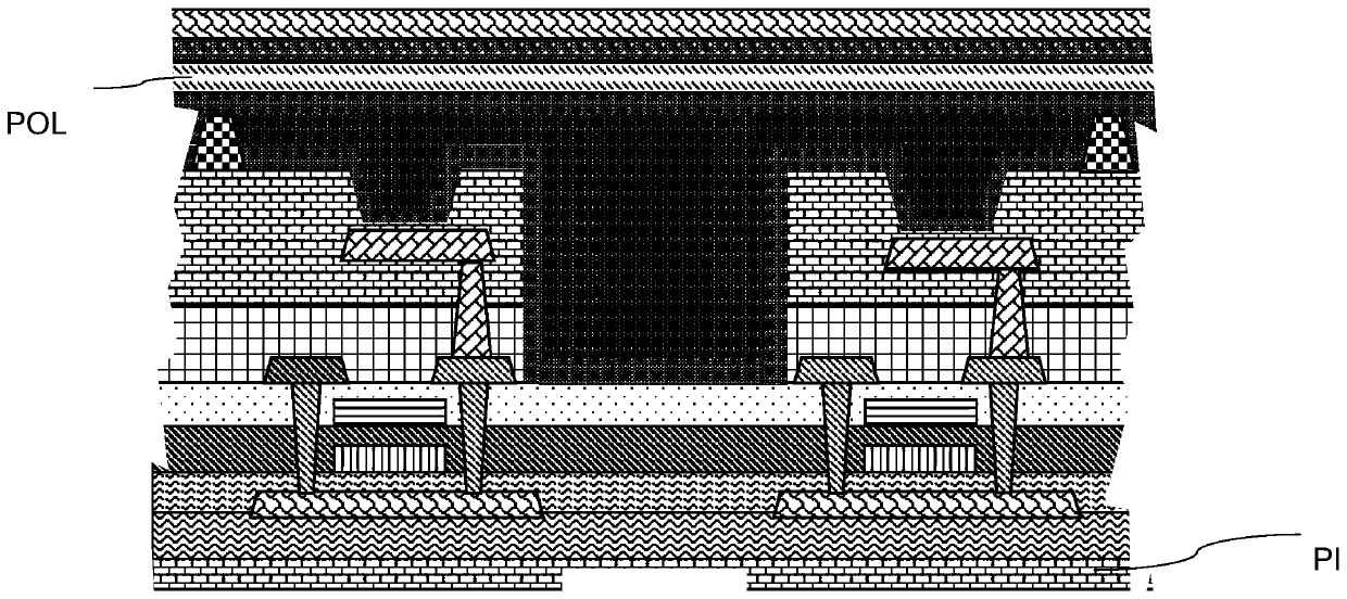
The invention provides a display panel, which comprises an array substrate, an open slot, a film packaging layer, a color filter and a protective layer, wherein the array substrate has a display area,and there is sub-pixel areas and a non-pixel area located between the sub-pixel areas in the display area; the open slot is arranged in the array substrate and corresponds to the non-pixel area; thefilm packaging layer is arranged on the array substrate; the color filter covers the film packaging layer; the protective layer covers the side, which is away from the film packaging layer, of the color filter; the protective layer is provided with a through hole, the through hole runs through the protective layer and the color filter and reaches the side, which is away from the array substrate, of the film packaging layer, and the through hole corresponds to the open slot. The display panel replaces a polarizer with the structure of a color film substrate, a black matrix and the protective layer. The part of a camera shooting area corresponding to the color film substrate and the protective layer is punched and filled with a transparent material with high transmittance, thereby enabling the light to better pass through and be transmitted to a camera module below the open slot area, and finally improving the camera shooting performance.

Description

technical field [0001] The present invention relates to the technical field of liquid crystal display, and in particular, to a display panel. Background technique [0002] Due to the appearance of the screen concept, the corresponding high-specification requirements have also been generated with the development of technology. The invention proposes an easy-to-fold, ultra-thin foldable screen design based on the screen. Combined with the appearance concept of the camera area that appears on the market at this stage, further optimization is carried out to reduce the thickness of the screen, which is easy to bend, and at the same time improve the light transmittance, so that the performance of the camera module can be better played. [0003] Due to the trend of thin, deformable and full-screen mobile phones in existing mobile phones, one of the ways to achieve full screen is to hide the camera module in the panel, and in order to ensure that the camera module can receive more ...

Claims


Application Information

Patent Timeline
IPC IPC(8): H01L27/32H01L51/00H01L51/52
CPCH10K59/38H10K59/12H10K77/111H10K50/865H10K50/844Y02E10/549
Inventor 郑敏欧阳齐周阳
Owner WUHAN CHINA STAR OPTOELECTRONICS SEMICON DISPLAY TECH CO LTD
Learn More