Lens and LED light source device adopting same

A technology of LED light source and LED bracket, applied in the optical field, can solve the problems of weak light control ability, low brightness of light source devices, and more stray light, etc.

Pending Publication Date: 2019-08-02
XI AN RAYSEES TECH CO LTD
View PDF3 Cites 0 Cited by
  • Summary
  • Abstract
  • Description
  • Claims
  • Application Information

AI Technical Summary

Problems solved by technology

[0003] The purpose of the embodiments of the present invention is to provide a lens, aiming to solve the problem that the existing lens has weak light control ability, resulting in more stray light and low brightness of the light source device

Method used


Image

  • Lens and LED light source device adopting same
  • Lens and LED light source device adopting same
  • Lens and LED light source device adopting same

Examples


Embodiment Construction

[0049] In order to make the object, technical solution and advantages of the present invention clearer, the present invention will be further described in detail below in conjunction with the accompanying drawings and embodiments. It should be understood that the specific embodiments described here are only used to explain the present invention, not to limit the present invention.

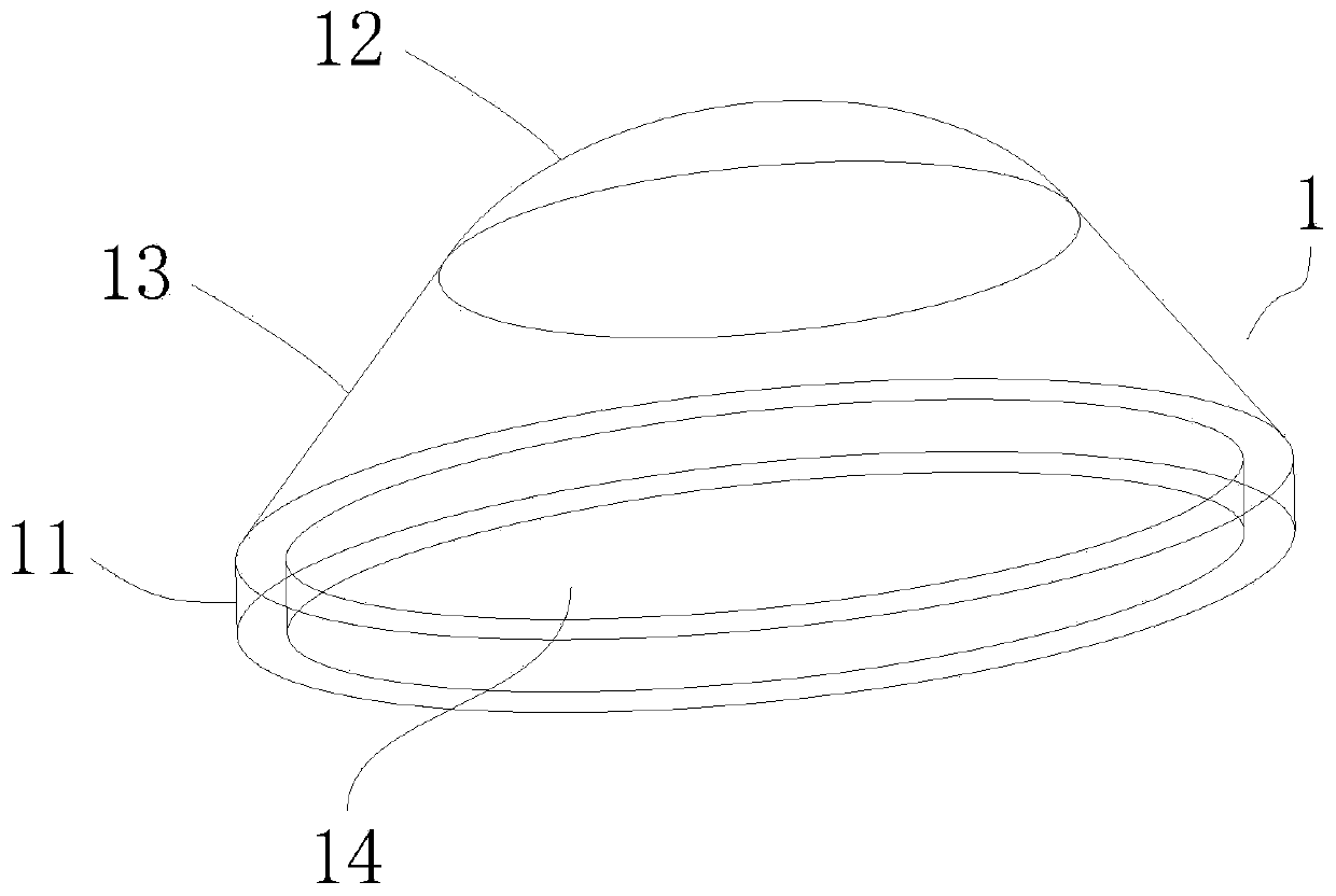
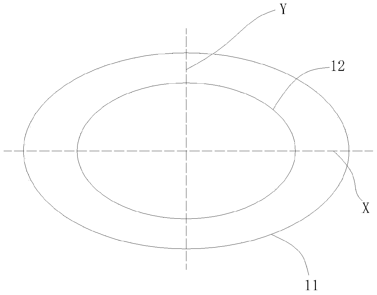
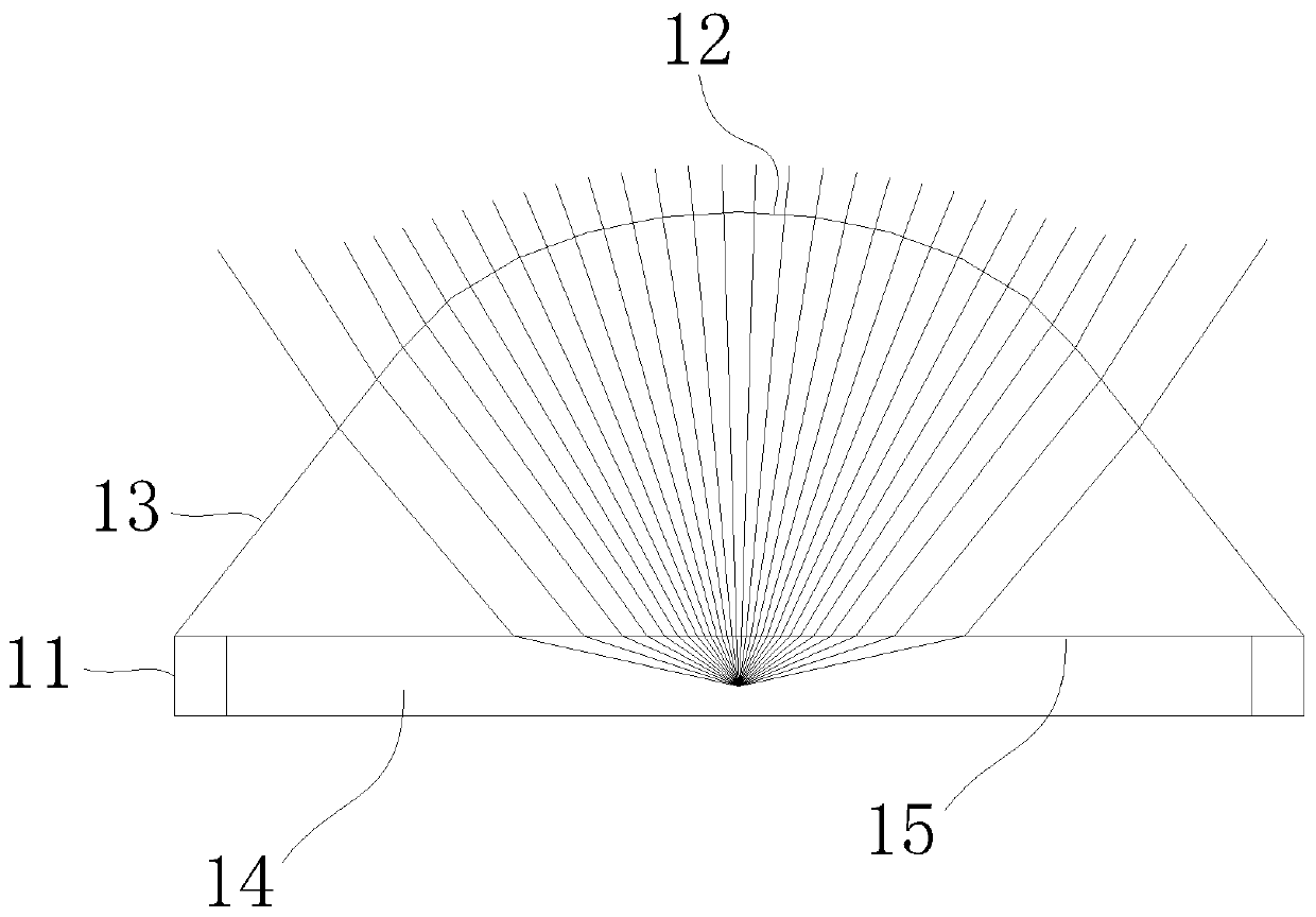
[0050] The lens provided by the embodiment of the present invention has an elliptical base, an ellipsoidal upper part, and a main body connecting the elliptical base and the ellipsoidal upper part, and the elliptical base is provided with a concave cavity for accommodating LED chips. The ratio of the minor axis to the major axis of the ellipsoidal upper part is 0.1-1.0; wherein, the ratio of the major axis to the minor axis of the elliptical base is equivalent to the ratio of the major axis to the minor axis of the ellipsoidal upper part. In this way, the light emitted by the LED chip is firstly re...


PUM


Abstract

The invention is applicable to the technical field of optics, and provides a lens. The lens is provided with an elliptical base, an elliptical upper part and a main body connecting the elliptical baseand the elliptical upper part, wherein the elliptical base is provided with a concave cavity used for accommodating an LED wafer, and the ratio of the short axis to the long axis of the elliptical upper part is 0.1-1.0. The light emitted by the LED wafer is firstly refracted into the lens through the top surface of the concave cavity and then refracted to a preset illumination area through the surfaces of the main body and the elliptical upper part. The stray light around the preset illumination area is greatly reduced, the effective light intensity in the center is correspondingly enhanced,and the requirements of various LED light source devices, especially an infrared emitter tube, for the spot brightness and uniformity are fully met. In addition, according to the LED light source device provided by the embodiment of the invention, an LED support and the bottom of the lens are bounded by adhesive glue, and the area between the side surface of the concave cavity and the side surfaceof the LED wafer is also filled with the adhesive glue, so that the bonding surface between the lens and the LED support is greatly expanded, the firmness of the lens support is also greatly enhanced, and thus the failure rate caused by the lens falling off from the LED support is greatly reduced.

Description

technical field [0001] The invention belongs to the field of optical technology, in particular to a lens and an LED light source device using the lens. Background technique [0002] Today, various LED light source devices have higher and higher requirements for light efficiency and brightness. In addition to LED chips, lenses are also a very important factor. However, the existing primary lens has weak light control ability, resulting in more stray light and low brightness of the light source device, especially unable to meet the requirements of the infrared emission tube for the brightness and uniformity of the light spot. In addition, the light spot emitted from the existing LED light source device presents a situation of strong center and weak edge, which is not conducive to direct use, and needs to be optimized by software, which is complicated and cumbersome to use. Contents of the invention [0003] The purpose of the embodiments of the present invention is to provi...

Claims


Application Information

Patent Timeline
Patent Type & Authority Applications(China)
IPC IPC(8): H01L33/48H01L33/58F21V5/04F21V17/10F21Y115/10
CPCH01L33/483H01L33/58F21V5/04F21V17/101F21Y2115/10
Inventor 汪洋
Owner XI AN RAYSEES TECH CO LTD
Why Eureka
Try Eureka