Ultra-short female connector of electric plug connector
A technology of electric plug connectors and plug connectors, which is applied in the direction of conductive connection, connection, fixed connection, etc., can solve the problems of inconvenient use, large volume, and use of dense network power distribution cabinets, and achieve the effect of reducing the size of the product
- Summary
- Abstract
- Description
- Claims
- Application Information
AI Technical Summary
Problems solved by technology
Method used
Image
Examples
Embodiment 1
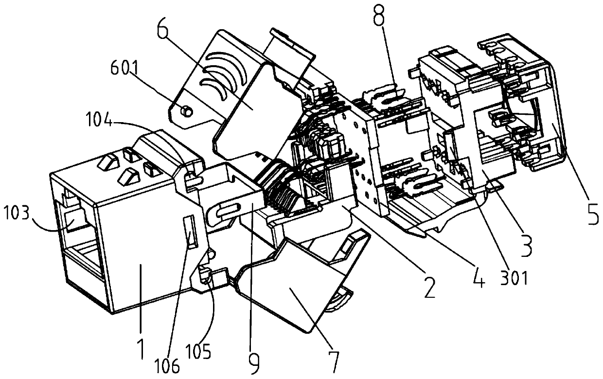
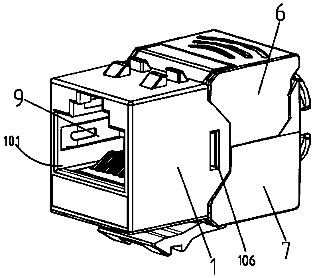
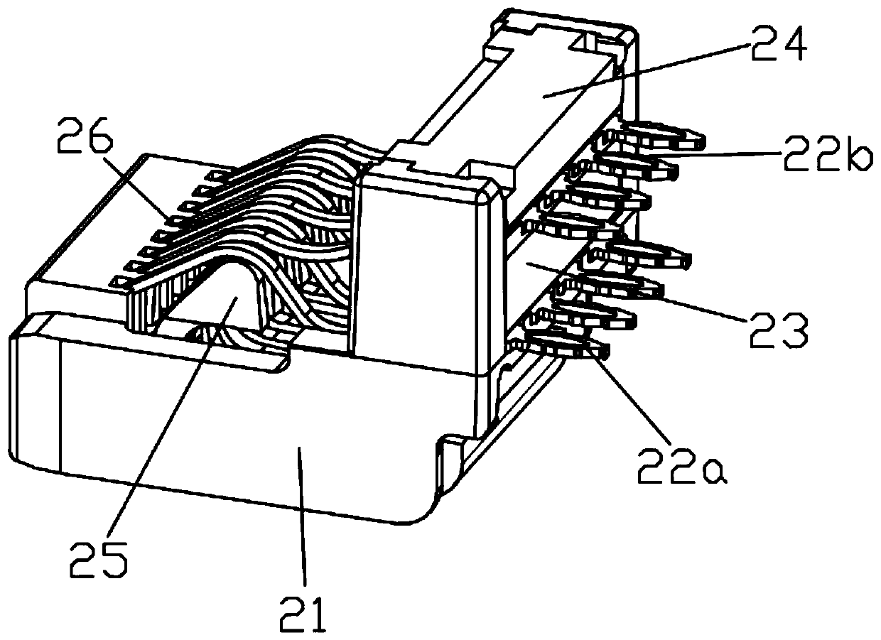
[0041] see figure 1 , figure 2 As shown, an ultra-short electric plug connector female base includes a plug connector housing 1, the front end of the plug connector housing 1 is an RJ45 network interface 101, and the rear end is an opening. The plug connector housing 1 is provided with a direct pressure ferrule 2, the rear end of the plug connector housing 1 is clamped with a terminal base 3, and the front end of the terminal base 3 is provided with a PCB circuit board 4. The rear end of the terminal block 3 is provided with a wiring cover 5, the front of the PCB circuit board 4 is connected with the first group of connecting elements on the direct pressure ferrule 2, and the back of the PCB circuit board 4 is provided with There is a second group of connecting elements 8 connected to the terminal base 3; an upper buckle 6 is pivotally connected above the rear end of the plug connector housing 1, and the rear end of the plug connector housing 1 The lower pivot is connected ...
Embodiment 2
[0056] This embodiment provides an ultra-short type electric plug connector female seat, its overall structure is consistent with the electric plug connector female seat in Embodiment 1, the difference is that: the upper buckle 6, the lower The wire management mechanisms used to manage the routing of the cables on the buckle 7 are different. Specifically, see Figure 14, The wire management mechanism in this embodiment includes a wire buckle 73, a wire buckle base 71 and a wire support cover 72, the wire buckle base 71 is integrally formed with the lower buckle 7, and is fixedly installed on the lower buckle 7. The wire support cover 72 is installed on the upper buckle 6, and when the upper buckle 6 and the lower buckle 7 are fastened together, a hole for cable routing is formed between the wire support cover 72 and the buckle base 71. aisle. The top of the drag line cover 72 is provided with the snap-line buckle 73, one end of the snap-line buckle 73 is hinged on the first ...
Embodiment 3
[0058] This embodiment provides an ultra-short electric plug connector female base, its overall structure is consistent with the electrical plug connector female base in Embodiment 1, the difference is that:
[0059] 1. The upper buckle 6 and the lower buckle 7 have different wire management mechanisms for managing the routing of cables. Specifically: see Figure 15 , Figure 16 As shown, the outer side of the lower fastening part 7 is provided with a semi-arc-shaped lower threaded plate 7-1, and the upper fastening part 6 is provided with a semi-circular-shaped upper threaded plate 6-1. When the upper fastening part 6 and the lower fastening part 7. After snapping together, the lower threaded plate 7-1 and the upper threaded plate 6-1 fit each other, and the threads formed on the lower threaded plate 7-1 and the upper threaded plate 6-1 fit together can be used for fastening nuts 10 turns Tight external thread. The lower threaded plate 7-1 located at the junction of the lo...
PUM
| Property | Measurement | Unit |
|---|---|---|
| Size | aaaaa | aaaaa |
| Bend angle | aaaaa | aaaaa |
Abstract
Description
Claims
Application Information
 - R&D
- Intellectual Property
- Life Sciences
- Materials
- Tech Scout
- Unparalleled Data Quality
- Higher Quality Content
- 60% Fewer Hallucinations
Browse by: Latest US Patents, China's latest patents, Technical Efficacy Thesaurus, Application Domain, Technology Topic, Popular Technical Reports.
© 2025 PatSnap. All rights reserved.Legal|Privacy policy|Modern Slavery Act Transparency Statement|Sitemap|About US| Contact US: help@patsnap.com


