Method for calculating radiance of main shaft shielding part of double-sided component, equipment and medium

A calculation method and emissivity technology, applied in the field of emissivity calculation at the occlusion of the main shaft of a double-sided module, can solve the problem of lack of estimation methods, and achieve the effect of improving the accuracy

Pending Publication Date: 2021-07-23
POWERCHINA HUADONG ENG COPORATION LTD +1
View PDF0 Cites 0 Cited by
  • Summary
  • Abstract
  • Description
  • Claims
  • Application Information

AI Technical Summary

Problems solved by technology

In the traditional technical solution, the usual algorithm of the backside shading ratio does not consider the height of the main axis from the back of the module, and directly designs the backside shading ratio of the bifacial module as the shading ratio, but this method will amplify the influence of shading, and the bottom line The reason is that although the main shaft blocks part of the light and creates shadows on the cell, in fact, because the direction of the light is uncertain, the shadowed part can still generate power, but the proportion of this part of the power to the original power is Compared with the impact, but there is no effective estimation method

Method used


Image

  • Method for calculating radiance of main shaft shielding part of double-sided component, equipment and medium
  • Method for calculating radiance of main shaft shielding part of double-sided component, equipment and medium
  • Method for calculating radiance of main shaft shielding part of double-sided component, equipment and medium

Examples


Embodiment 1

[0044] Such as figure 1 , 3 As shown, this embodiment provides a method for calculating the radiation rate at the shielded position of the main axis of the bifacial module, including:

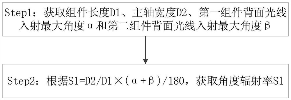
[0045] Step1: Obtain the component length D1, the main axis width D2, the maximum angle α of the incident light on the back of the first component, and the maximum angle β of the incident light on the back of the second component;

[0046] Step2: According to the length D1 of the component, the width D2 of the main axis, the maximum incident angle α of the light on the back of the first component and the maximum angle β of the incident light on the back of the second component, obtain the direct radiation rate S1 at the occluded place of the main axis; preferably ,according to Obtain the direct radiation rate S1 at the shielded place of the main axis.

[0047] In the traditional technology, the impact of the bracket on the photovoltaic power generation is generally calculated by comparing t...

Embodiment 2

[0051] Such as figure 2 , 3 As shown, this embodiment provides a method for calculating the radiation rate at the shielded position of the main axis of the bifacial module, including:

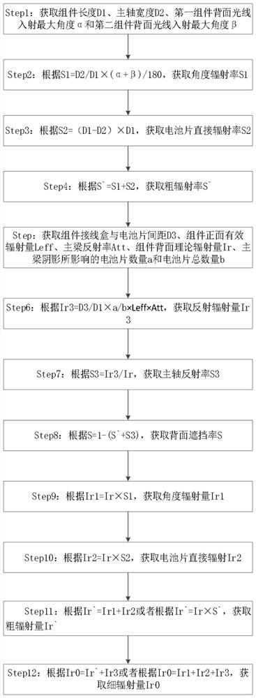
[0052] Step1: Obtain the component length D1, the main axis width D2, the maximum angle α of the incident light on the back of the first component, and the maximum angle β of the incident light on the back of the second component;

[0053] Step2: According to Obtain the direct radiation rate S1 at the shielded place of the main axis.

[0054] Step3: Obtain the radiation rate S2 at the unshielded position on the back; preferably, according to Obtain the radiation rate S2 of the unshielded part on the back;

[0055] Step4: According to S`=S1+S2, obtain the rough radiation rate S`.

[0056] In this embodiment, it is not only necessary to calculate the direct radiation rate S1 at the shielded part of the main axis, but also to evaluate the overall radiation rate. The affected emissivity of...

Embodiment 3

[0070] This embodiment provides an electronic device, including a processor, a memory, and a computer program stored in the memory and operable on the processor. The processor is used to execute the computer programs stored in the memory. The program realizes the method for calculating the radiation rate at the shaded position of the main axis of the bifacial module described in Embodiment 1 or 2.

[0071] The device may be a desktop computer, a notebook, a palmtop computer, a tablet computer, a mobile phone, a human-computer interaction screen and the like. The device may include, but is not limited to, a processor, memory. Those skilled in the art can understand that this is only an example of the device and does not constitute a limitation to the device, and may include more or less components than those shown in the illustration, or combine certain components, or different components, for example: the device It may also include input / output interfaces, display devices, ne...


PUM


Abstract

The invention discloses a method for calculating the radiance of a main shaft shielding part of a double-sided component, equipment and a medium. The method comprises the following steps: acquiring the length D1 of the component, the width D2 of the main shaft, the maximum incident angle alpha of light on the back surface of a first component and the maximum incident angle beta of light on the back surface of a second component; and obtaining the direct radiance S1 of the main shaft shielding part. The method has the technical effects that by calculating the proportion of the power of the batteries irradiated on the battery pieces from the two sides of the main shaft to the total theoretical radiation quantity of the back face of the component, the defect that in an original technical scheme, calculation is conducted simply according to the length of the component and the width of the main shaft is overcome; the method achieves the estimation of the total theoretical radiation quantity of the power of the batteries irradiated on the battery pieces from the two sides of the main shaft on the back side of the component, and further improves the precision of the estimation of the influence of the power generated by the main shaft.

Description

technical field [0001] The invention relates to the field of photovoltaic power generation, in particular to a method, device and medium for calculating the radiance of a main shaft shielded part of a double-sided module. Background technique [0002] For a bifacial module installed vertically on a flat single-axis tracker, usually the central position of the back of the bifacial module will be blocked by the main axis, and the shading mainly affects the back radiation near the main axis. In the traditional technical solution, the usual algorithm of the backside shading ratio does not consider the height of the main axis from the back of the module, and directly designs the backside shading ratio of the double-sided module as the shading ratio, but this method will amplify the influence of shading, and the bottom line The reason is that although the main shaft blocks part of the light and creates shadows on the cell, in fact, because the direction of the light is uncertain, ...

Claims


Application Information

Patent Timeline
Patent Type & Authority Applications(China)
IPC IPC(8): G06F17/15
CPCG06F17/15
Inventor 吴芳和王顺波俞琨孙长江曹家兴黄圭成田鹏杨宏毅王士涛李彩霞
Owner POWERCHINA HUADONG ENG COPORATION LTD
Why Eureka
Try Eureka