Dual-frequency patch antenna capable of widening beam width

A technology of beam width and patch antenna, which is applied in the field of wireless communication, can solve problems such as difficult processing, high profile, and complex structure, and achieve the effect of easy processing, simple processing, and narrow beam width

Active Publication Date: 2021-03-19
SHENZHEN UNIV
View PDF5 Cites 0 Cited by
  • Summary
  • Abstract
  • Description
  • Claims
  • Application Information

AI Technical Summary

Problems solved by technology

[0004] The technical problem to be solved by the present invention is to design a dual-band width beam antenna. In addition to realizing dual-band and widened beam

Method used


Image

  • Dual-frequency patch antenna capable of widening beam width
  • Dual-frequency patch antenna capable of widening beam width
  • Dual-frequency patch antenna capable of widening beam width

Examples


Embodiment 1

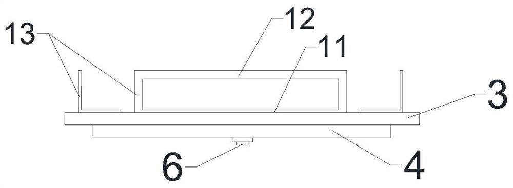
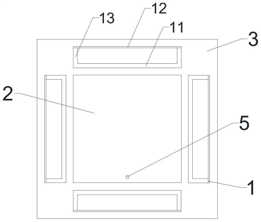
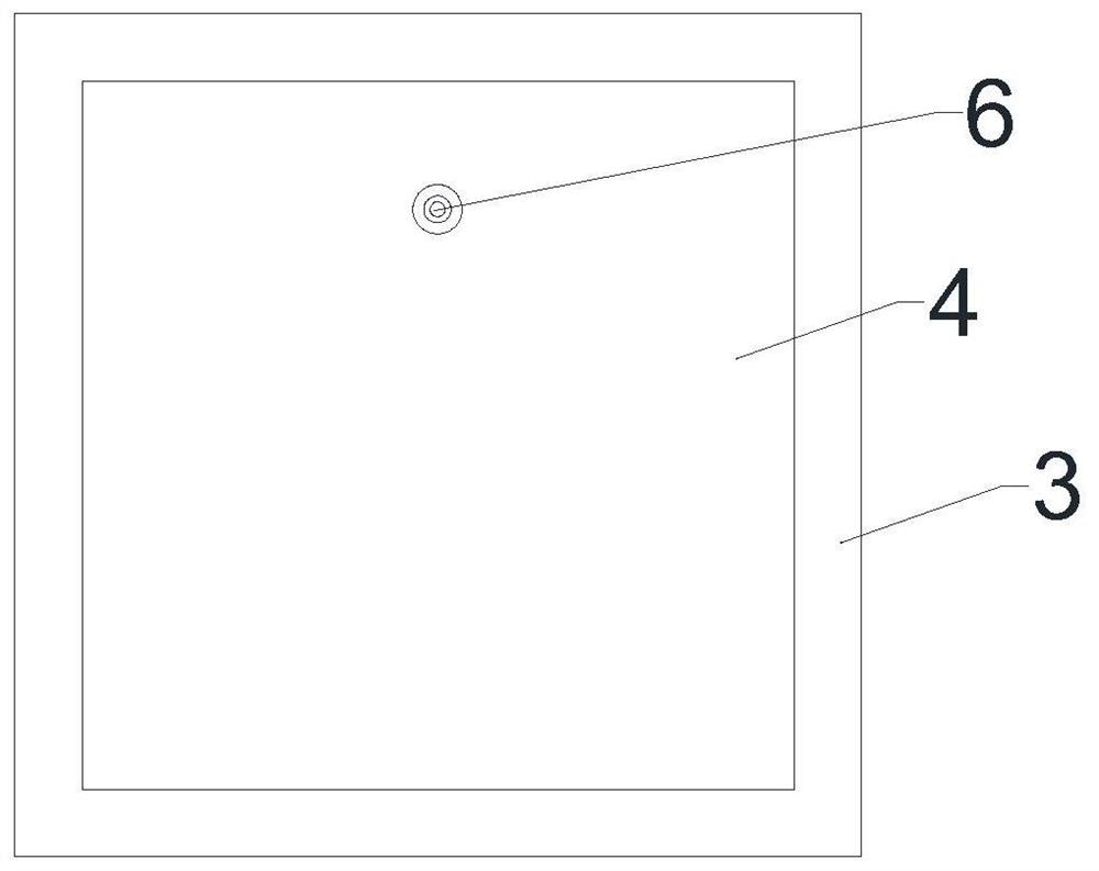
[0029] see figure 1 , figure 2 as well as image 3 , a dual-frequency patch antenna with broadened beamwidth, including sequentially stacked radiation layer, dielectric layer 3 and metal floor 4, and also includes a feeder, the radiation layer is composed of radiation patch 2 and parasitic on the radiation The metal folded ring 1 around the patch 2 is formed, and the feeder feeds the radiation patch 2; the metal folded ring 1 includes a radiation segment 12 and a coupling segment 11, and the coupling segment 11 is connected to the radiation The patch 2 is coupled, and the plane where the radiating segment 12 is located is perpendicular to the radiating patch 2 .

[0030] By loading the parasitic folded metal ring 1 to generate a vertical current, an additional beam is obtained to achieve the purpose of widening the beam width, and the half-wavelength parasitic folded metal ring 1 excites a new resonance mode to form a dual frequency. Therefore, using the parasitic metal fo...

Embodiment 2

[0032] On the basis of the above structure, there are at least two folded metal rings 1 , and the radiation layer is mirror-symmetrical to the central axis of the radiation patch 2 to optimize half-power beam width and widening effect of bandwidth. The coupling segment 11 is located on the same plane as the radiation patch 2, which optimizes half-power beam width and widening effect of bandwidth.

Embodiment 3

[0034] On the basis of the above structure, the projections of the radiation patch 2 all fall in the metal floor 4, the projections of the metal floor 4 all fall in the medium layer 3, and the projections of the metal folding ring 1 all fall falls on the medium layer 3. That is, the area (size) of the metal floor 4 is larger than the area (size) of the radiation patch 2 but smaller than the area (size) of the dielectric layer 3 . Without changing the structure of the antenna, the communication system reduces the backward radiation of the antenna by controlling the size of the metal floor 4, and contributes more beam width to the direct upward radiation direction to further expand the beam width. Since the metal folding ring 1 is parasitic on the periphery of the radiation patch 2 , the projection of the metal folding ring 1 does not overlap with the projection of the radiation patch 2 .


PUM

PropertyMeasurementUnit
Resonant frequencyaaaaaaaaaa

Abstract

The invention provides a dual-frequency patch antenna capable of widening beam width, which comprises a radiation layer, a dielectric layer and a metal floor which are stacked in sequence, and furthercomprises a feeder. The radiation layer is composed of a radiation patch and a metal folding ring parasitic at the periphery of the radiation patch, and the feeder feeds the radiation patch. The metal folding ring comprises a radiation segment and a coupling segment, the coupling segment is coupled with the radiation patch, and the plane where the radiation segment is located is perpendicular tothe radiation patch. A simple and easy-to-process structure is adopted, the beam width is broadened, and the beam width is increased by 30%. Double-frequency bandwidth broadening is achieved through single feed so as to meet the requirements of different application scenes, the defects that an existing antenna is narrow in beam width and high in profile are overcome, and high performance compatibility and structural miniaturization are achieved. Under the condition that the antenna profile is hardly increased, the half-power beam width can be flexibly broadened according to the requirement ofsignal coverage, and the quality of signal coverage is improved.

Description

technical field [0001] The invention relates to the technical field of wireless communication, in particular to a dual-frequency patch antenna capable of widening the beam width. Background technique [0002] In modern wireless communication systems, dual-band wide-beam antennas are popular in the market because they can achieve a wider range of radiation than traditional antennas. Extendable beam width antennas are a key technology in contemporary information technology applications. The multi-frequency application system must be well resolved to meet the application requirements of antenna small size, light weight, easy installation and dual-frequency or multi-frequency coverage; currently, the multi-frequency antenna design on the market often adopts stacking Layer structure, ignoring the performance of the antenna unit itself, the designed antenna often has a complex structure and a high profile. Although a wide beamwidth can be achieved by loading the structure, perfor...

Claims


Application Information

Patent Timeline
IPC IPC(8): H01Q1/38H01Q1/50
CPCH01Q1/38H01Q1/50
Inventor 钟增培张晓卢城知袁涛
Owner SHENZHEN UNIV
Why Eureka
Try Eureka