Separating device which can be arranged between two mountings

A technology for separating devices and mounting parts, which is applied in the direction of friction clamping detachable fasteners, connecting components, threaded fasteners, etc., and can solve problems such as difficult installation of separating devices

Inactive Publication Date: 2019-08-02
A RAYMOND & CO
View PDF2 Cites 0 Cited by
  • Summary
  • Abstract
  • Description
  • Claims
  • Application Information

AI Technical Summary

Problems solved by technology

Small, confined spaces make separation device installation difficult

Method used


Image

  • Separating device which can be arranged between two mountings
  • Separating device which can be arranged between two mountings
  • Separating device which can be arranged between two mountings

Examples


Embodiment Construction

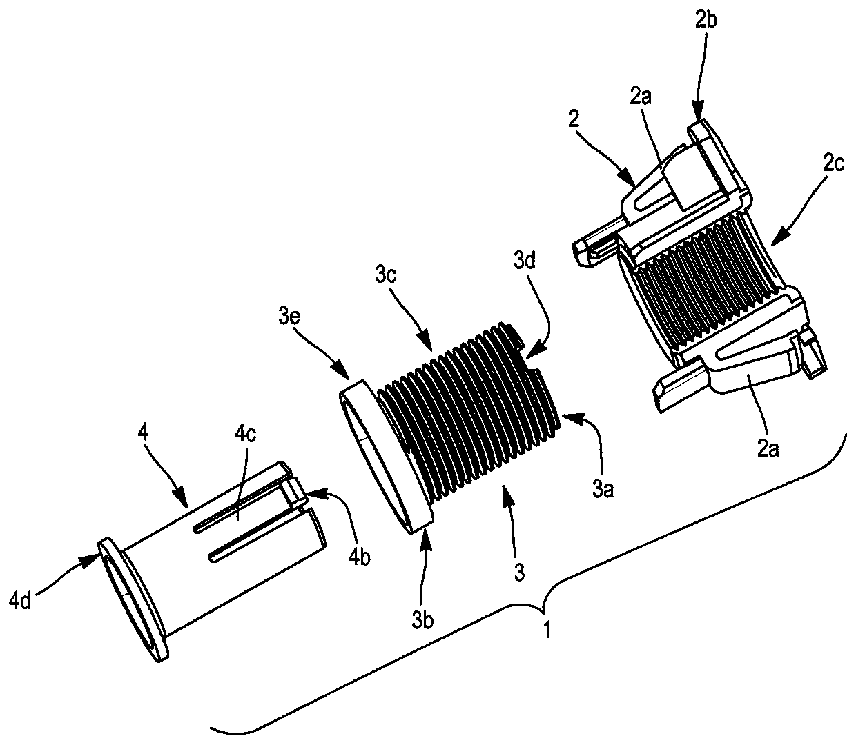
[0027] The separating device according to the invention is used to fill the space between a first mounting part and a second mounting part arranged opposite to each other. The term "inner face" refers to the faces of the first and second mounts which lie opposite each other; the term "outer face" refers to the faces of the first and second mount which are opposite these inner faces. The distance between the first and second mount is not precisely known, and the device of the invention makes it possible to compensate for these differences that may exist from one point of the mount to another. In this way, multiple separating devices can be placed between the mounts to more precisely control the distance separating them over their entire length.

[0028] Typically, these mounts are flat, at least around where the breakaway is mounted. The two mounts may have an angular offset and may not be perfectly parallel to each other.

[0029] The first and second mounts each have an ope...


PUM


Abstract

The invention relates to a separating device (1) comprising an attachment part (2) and a separating part (3). The attachment part and the separating part are assembled together and can move relative to one another in an axial direction in order to adjust the separating device. The separating device comprises a driving ring (4), accommodated in the separating part and capable of being rotated by atool, the driving ring comprising at least one first coupling means (4b) capable of engaging with a second coupling means (3d) of the separating part (3), forming a claw system, for selectively coupling and uncoupling the driving ring and the separating part.

Description

technical field [0001] The invention relates to a separating device that can be placed between two mountings in such a way as to bridge the distance between the two mountings. The invention has particular application in the automotive sector to fill the space between the carrier element and the roof body of a vehicle and to allow, for example, the fixing of a roof bar on the vehicle. Background technique [0002] From document EP2532568 is known a separating device designed to fill the spaces between the sheet metal elements making up the structure of the vehicle and to compensate for any dimensional differences that may exist between these elements. This known detaching device comprises an attachment part for resting and / or fixing on a first mounting part and a detaching part having a support end for contacting a second mounting part placed relative to the first mounting part . The attachment part and the detachment part are threaded together allowing their movement relat...

Claims


Application Information

Patent Timeline
Patent Type & Authority Applications(China)
IPC IPC(8): F16B5/02F16B37/04
CPCF16B5/0233F16B37/043F16B37/044F16B2/02F16B5/02
Inventor D·拉穆勒
Owner A RAYMOND & CO
Why Eureka
Try Eureka