Adjusting and positioning mechanism for parts at high-speed milling center

A technology of high-speed milling and positioning mechanism, which is used in large fixed members, metal processing machinery parts, metal processing equipment, etc., can solve the problems of repeated adjustment, loss of positioning effect, and decrease in stiffness of the joint surface, and achieves good positioning accuracy retention. , The position is easy to precisely control, and the effect of reducing the joint stiffness

Active Publication Date: 2012-04-18
SHENYANG MACHINE TOOLGRP RES & DESIGN INST CO LTD SHANGHAI BRANCH
View PDF4 Cites 0 Cited by
  • Summary
  • Abstract
  • Description
  • Claims
  • Application Information

AI Technical Summary

Problems solved by technology

The precise positioning between the basic parts of the machine tool of existing products is generally realized by self-made T-shaped positioning keys and inclined plane keys, but practice has proved that the positioning method of the positioning keys has the following limitations: 1. The positioning accuracy is not easy to maintain for a long time, because The use of positioning keys inevitably requires machining of key grooves on the joint surface, resulting in a decrease in the stiffness of the joint surface, which often deforms under the action of cutting force and torque, thus losing its positioning function; 2. High production costs, T-shaped positioning keys The bevel key and the bevel key are all self-made parts, and the bevel with special angle needs to be processed; 3. The manufacturing cycle is long, and special tools are required to insert and pull out the positioning key during assembly and adjustment, and the position is not easy to accurately control and needs to be adjusted repeatedly

Method used


Image

  • Adjusting and positioning mechanism for parts at high-speed milling center
  • Adjusting and positioning mechanism for parts at high-speed milling center
  • Adjusting and positioning mechanism for parts at high-speed milling center

Examples


Embodiment Construction

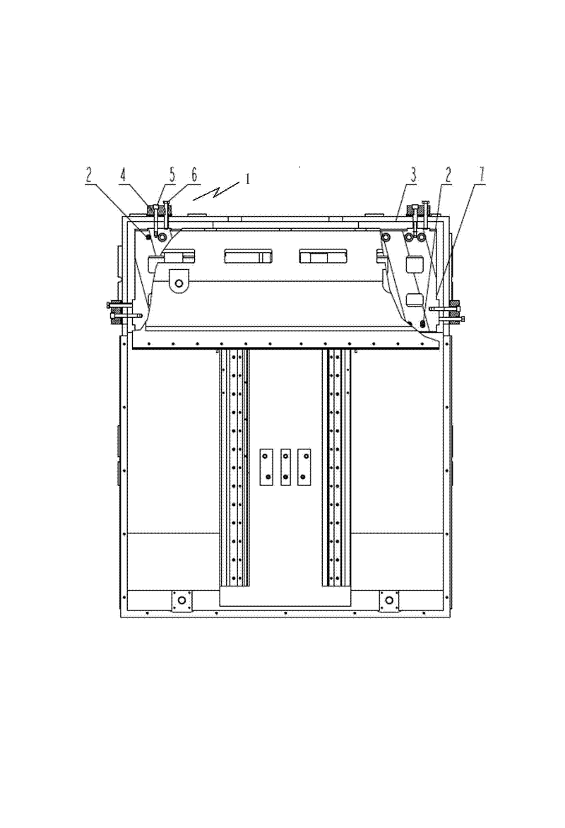
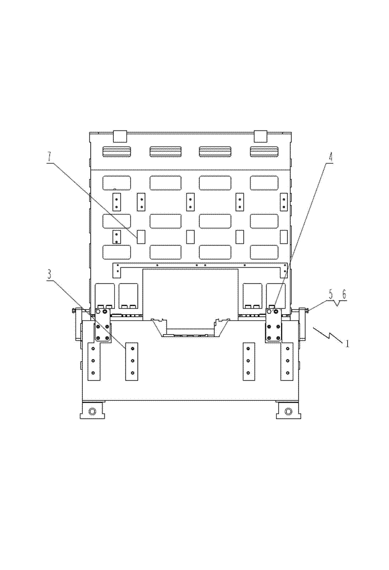
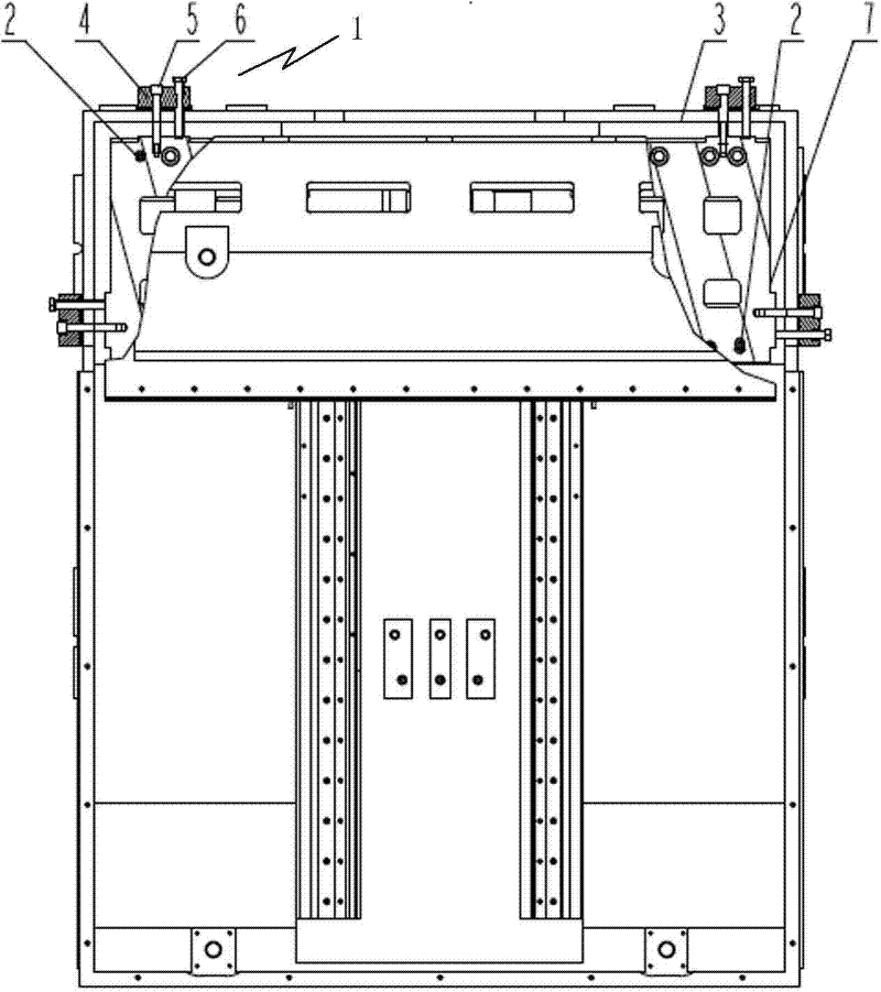
[0010] Such as figure 1 and 2 As shown, a high-speed milling center component adjustment and positioning mechanism is composed of four sets of screw mechanisms 1 and two positioning pins 2. The screw mechanism 1 is distributed on the side and rear of the base component 3 of the high-speed milling center. The positioning The pins 2 are distributed diagonally on the base part 1, and the positioning pins 2 are connected with the adjustment part 7 of the high-speed milling center, and the positioning pins 2 can be internal threaded conical pins.

[0011] The screw mechanism 1 includes an adjustment bracket 4, a hexagon socket head cap screw 5 and a fully threaded hexagon head bolt 6, wherein the adjustment bracket 4 is connected to the base part 3, and the hexagon socket head cap screw 5 is connected to the adjustment part 7 through the adjustment bracket 4, The full-threaded hex head bolt 6 is flexibly connected with the adjustment bracket 4.

[0012] The movement principle of...


PUM


Abstract

The invention relates to an adjusting and positioning mechanism for parts at a high-speed milling center. The mechanism is composed of four screw mechanisms and two positioning pins, wherein the screw mechanisms are distributed at the side and rear of a reference part at the high-speed milling center; and the positioning pins are diagonally distributed on the reference part, and the positioning pins are connected with an adjusting component at the high-speed milling center. The mechanism has the advantages of simple structure and short manufacturing cycle, and the position is easy to control accurately during assembly adjusting without repeated adjusting.

Description

technical field [0001] The invention relates to a component adjustment and positioning mechanism, in particular to the adjustment and positioning of high-speed milling center adjustment components. Background technique [0002] The adjustment and positioning mechanism is generally designed between the basic components of the high-speed milling center, and its characteristics directly affect the accuracy retention, manufacturing cycle and cost of the machine tool. The precise positioning between the basic parts of the machine tool of existing products is generally realized by self-made T-shaped positioning keys and inclined plane keys, but practice has proved that the positioning method of the positioning keys has the following limitations: 1. The positioning accuracy is not easy to maintain for a long time, because The use of positioning keys inevitably requires machining of key grooves on the joint surface, resulting in a decrease in the stiffness of the joint surface, whic...

Claims


Application Information

Patent Timeline
Patent Type & Authority Patents(China)
IPC IPC(8): B23Q1/00
Inventor 关锡友刘春时李焱林剑峰张健侯延星徐吉存化春雷徐兆成赵雷高柏宏楚文龙张伟王迪张建中隋海倬侯春华王亮
Owner SHENYANG MACHINE TOOLGRP RES & DESIGN INST CO LTD SHANGHAI BRANCH
Why Eureka
Try Eureka