Beam shaping device, an optical head, and a master disk recording apparatus

Inactive Publication Date: 2004-10-14
PANASONIC CORP
View PDF6 Cites 0 Cited by
  • Summary
  • Abstract
  • Description
  • Claims
  • Application Information

AI Technical Summary

Problems solved by technology

Due to its lower mechanical precision and follow-up frequency, this optical head cannot be used in a master disk recor

Method used


Image

  • Beam shaping device, an optical head, and a master disk recording apparatus
  • Beam shaping device, an optical head, and a master disk recording apparatus
  • Beam shaping device, an optical head, and a master disk recording apparatus

Examples


Embodiment Construction

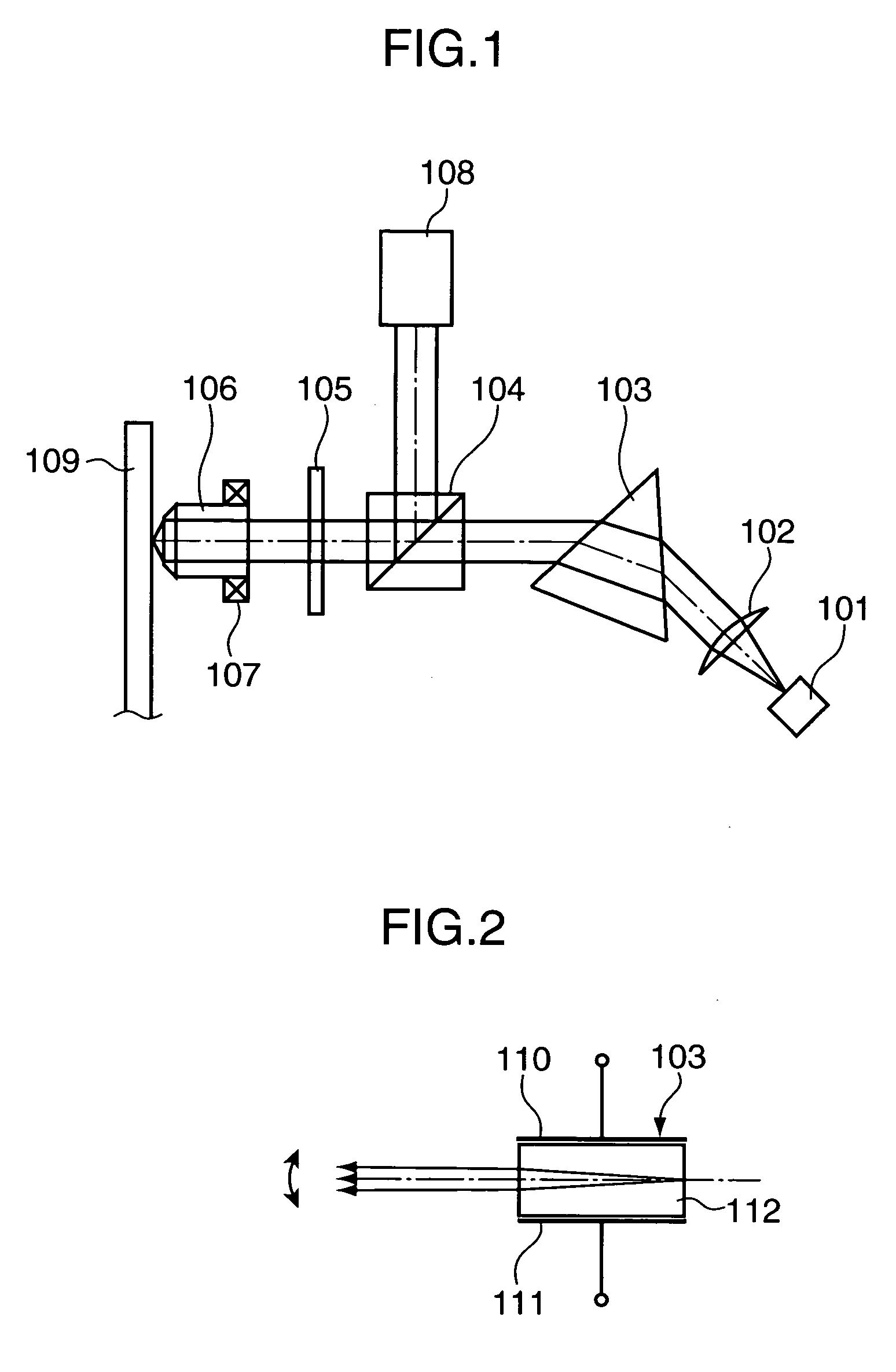
[0029] Hereinafter, an optical head according to one embodiment of the present invention is described with reference to the accompanying drawings. FIG. 1 is a schematic diagram showing a construction of an optical head according to one embodiment of the invention.

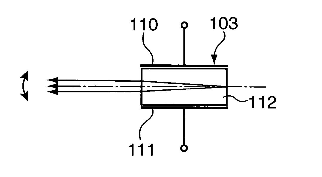
[0030] The optical head shown in FIG. 1 is provided with a light source 101, a lens 102, a beam shaping device 103, a polarized beam splitter 104, a .lambda. / 4 wavelength plate 105, an objective lens 106, an actuator 107 and a light detector 108.

[0031] The light source 101 is comprised of a semiconductor laser, e.g. a violet semiconductor laser having a wavelength of about 400 nm, and a light beam of a linearly polarized light is emitted from the light source 101 while spreading. Since the semiconductor laser is used as the light source 101, the intensity of the emitted light beam can be directly adjusted and modulated by driving the semiconductor laser using a specified driving circuit (not shown). It should be noted that ...


PUM


Abstract

A beam shaping device shapes a light beam from a light source to have a circular cross section, and changes the refractive index thereof by causing an electric field to be produced by a voltage applied to electrodes thereof. In this way, the light beam from the light source is deflected, and an objective lens gather the shaped and deflected light beam to expose an optical disk.

Description

[0001] 1. Field of the Invention[0002] The present invention relates to a beam shaping device for shaping a light beam, an optical head using such a beam shaping device, and a master disk recording apparatus using such an optical head.[0003] 2. Description of the Background Technology[0004] Conventionally, an optical head fabricated by miniaturizing and integrating a light source, an optical system and a detection system has been mounted on an optical disk drive to record information in an optical disk and reproduce the recorded information. FIG. 4 is a schematic diagram showing a construction of a conventional optical head. A light source 301 shown in FIG. 4 is comprised of a semiconductor laser, and emits a light beam having an elliptical cross section in the form of a linearly polarized light. The emitted light beam is introduced to a beam splitter 304 after being shaped to have a substantially circular cross section by a lens 302 and a prism-shaped beam shaping device 303. The l...

Claims


Application Information

Patent Timeline
IPC IPC(8): G02B3/00G02B27/09G02F1/29G11B7/00G11B7/085G11B7/125G11B7/135G11B7/1359G11B7/1398G11B7/26
CPCG02F1/29G11B7/08552G11B7/1359G11B7/1398G11B7/261
Inventor ABE, SHINYAITO, EIICHI
Owner PANASONIC CORP
Why Eureka
Try Eureka