
Cutting insert and cutting tool with adjustable structure

A technology of cutting tools and cutting inserts, which is applied to tools used in lathes, accessories of toolholders, turning equipment, etc., which can solve the problems that the adjustment mechanism cannot provide pre-tightening force, lose the adjustment of the cutting angle, etc., and achieve the radial direction of the insert. Large adjustment range, uniform distribution of cutting force, and improved overall stability

Active Publication Date: 2020-06-26
ZHUZHOU CEMENTED CARBIDE CUTTING TOOLS CO LTD
View PDF8 Cites 0 Cited by
  • Summary
  • Abstract
  • Description
  • Claims
  • Application Information

AI Technical Summary

Problems solved by technology

This patent eliminates the reverse force exerted by the adjustment structure on the blade during the cutting process, which further improves the adjustment accuracy, but loses the function of adjusting the cutting angle (that is, the axial angle of the cutterhead). no preload

Method used


Image

  • Cutting insert and cutting tool with adjustable structure
  • Cutting insert and cutting tool with adjustable structure
  • Cutting insert and cutting tool with adjustable structure

Examples


Embodiment 1

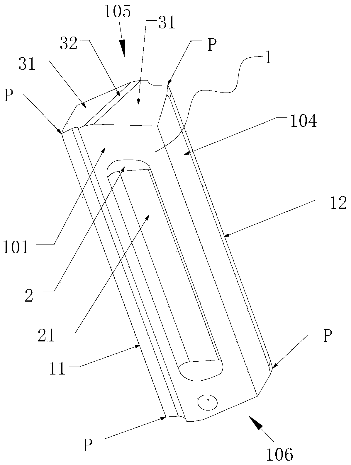
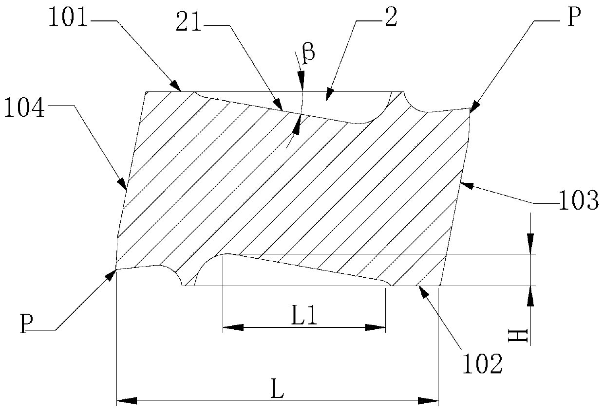
[0034] Such as figure 1 with figure 2 As shown, the cutting insert of this embodiment, the cutting insert 1 includes an upper end face 101, a lower end face 102, a first side 103, a second side 104, a third side 105 and a fourth side 106, the upper end 101 and the first side 103 The first cutting edge 11 is formed by intersecting, the second cutting edge 12 is formed between the lower end surface 102 and the second side surface 104, the second side surface 104 is located on the opposite side of the first side surface 103, and the upper end surface 101 is provided with a clamping groove 2, clamping There is a clamping slope 21 in the holding groove 2, and the angle between the clamping slope 21 and the upper end surface 101 is β, and β is an acute angle. In the direction from the second side 104 to the first side 103, the clamping slope 21 and the upper The distance H between the end faces 101 increases gradually, the first cutting edge 11 is center-symmetric about the second...

Embodiment 2

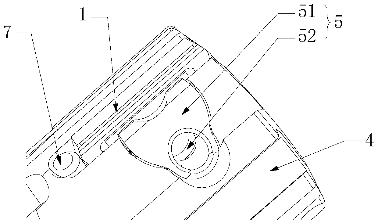
[0041] Such as Figures 3 to 7 As shown, the cutting tool with adjustable structure in this embodiment includes a cutter body 4, a blade pressing device 5 and a blade radial adjustment device 6, and the cutting tool also includes the cutting blade 1 of the above-mentioned embodiment 1, and on the cutter body 4 A sipe 41 and an adjustment installation groove 42 communicating with the sipe 41 are provided. The cutting blade 1 is installed in the sipe 41 and pressed by the blade pressing device 5 . F4 is the reaction force of the sipe 41 to the blade. The first cutting edge 11 and the first side surface 103 face outwards, the blade pressing device 5 has a pressing surface 501 matched with the clamping inclined surface 21, and the blade radial adjustment device 6 is arranged in the adjustment installation groove 42 for pushing the cutting blade 1 moves radially in the sipe 41, and the angle between the axis of the blade radial adjustment device 6 and the horizontal plane is θ, and...


PUM


Abstract

The invention discloses a cutting blade and a cutting tool provided with an adjustable structure. The cutting blade comprises an upper end face, a lower end face, a first side face, a second side face, a third side face and a fourth side face, wherein the upper end face interacts with the first side face to form a first cutting edge, and a second cutting edge is formed between the lower end face and the second side face; the second side face is located opposite to the first side face; a clamping groove is formed in the upper end face, a clamping slope is arranged in the clamping groove, and anincluded angle beta between the clamping slope and the upper end face is an acute angle; in the direction from the second side face to the first side face, the distance H between the clamping slope and the upper end face becomes larger gradually; the first cutting edge is in central symmetry with the second cutting edge; and the upper end face is in central symmetry with the lower end face. The cutting tool comprises the cutting blade, a pressing device used for pressing the blade, and a radial adjustment device used for adjusting the blade. The radial adjustment range of the blade is wide, the pre-tightening force can change along with the change of the radial adjustment size and is more stable, and firmer locking is realized.

Description

technical field [0001] The invention relates to the technical field of metal cutting, in particular to a cutting blade and a cutting tool with an adjustable structure. Background technique [0002] In the metal cutting processing industry, the stability of cutting tools is becoming more and more important. The finishing machining of cutting tools has higher and higher requirements for machining stability, and the adjustable structure used by finishing tools and the indexable insert There must be a change in relative position. If the moving positioning surface formed by the position change between the indexable insert and the adjustable structure is subject to a relatively large cutting force during the cutting tool machining process, the stability of the adjustment structure and the insert will be affected. Affected to a certain extent, the current adjustment structure needs to tighten the target blade after the adjustment is completed, which unintentionally increases the di...

Claims


Application Information

Patent Timeline
Patent Type & Authority Patents(China)
IPC IPC(8): B23B27/16
CPCB23B27/1625
Inventor 荣刚刘敏李文学杨红星付宇鹏吕长江卞玲玲
Owner ZHUZHOU CEMENTED CARBIDE CUTTING TOOLS CO LTD
Learn More