Three-axis workpiece clamping seat for digital controlled lathe

A technology of CNC lathes and workpiece clamps, applied in the field of CNC lathes, can solve the problems of maintenance or actual control, reduce workpiece processing efficiency, increase the thickness of the clamping seat, etc., and achieve the effects of reducing labor input, improving processing efficiency, and reducing thickness.

Active Publication Date: 2019-08-06
肇庆市高讯数控设备有限公司
View PDF5 Cites 1 Cited by
  • Summary
  • Abstract
  • Description
  • Claims
  • Application Information

AI Technical Summary

Problems solved by technology

[0005] The purpose of the present invention is to provide a three-axis workpiece clamping seat for CNC lathe processing, so as to solve the problem that the superimposed use of multiple plates in the above background technology will lead to a substantial increase in the thickness of the clamping seat itself. The control is more troublesome; although the existing part of the clamping seat has the function of moving up and down the Z axis-that is, the function of rising and falling the workpiece, but this kind of function occupies too much space on the clamping seat on the one hand, and on the other hand, it only Simple lifting does not automatically reverse the vertical plane of the workpiece. Therefore, when the workpiece is processed, it needs to stop frequently to adjust the bottom of the workpiece to the position where the top of the workpiece is in contact with the tool, and greatly reduce the workpiece. The problem of processing efficiency

Method used


Image

  • Three-axis workpiece clamping seat for digital controlled lathe
  • Three-axis workpiece clamping seat for digital controlled lathe
  • Three-axis workpiece clamping seat for digital controlled lathe

Examples


Embodiment Construction

[0025] The following will clearly and completely describe the technical solutions in the embodiments of the present invention with reference to the accompanying drawings in the embodiments of the present invention. Obviously, the described embodiments are only some, not all, embodiments of the present invention. Based on the embodiments of the present invention, all other embodiments obtained by persons of ordinary skill in the art without making creative efforts belong to the protection scope of the present invention.

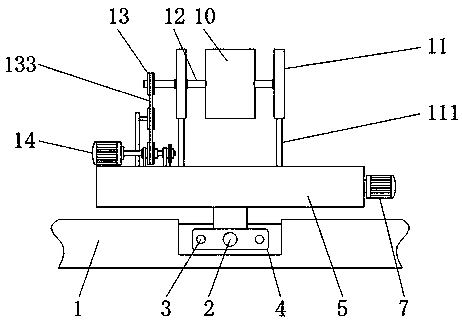
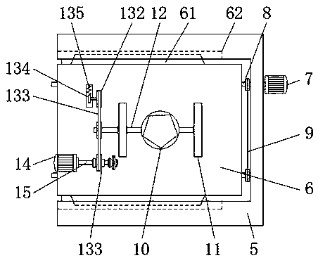
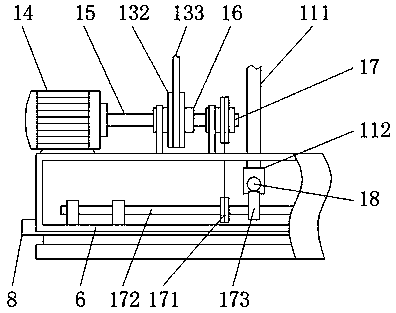
[0026] see Figure 1-7 , the present invention provides a technical solution: a three-axis workpiece clamping seat for CNC lathe processing, including a lathe base 1, a first screw rod 2, a slide rail 3, a displacement seat 4, a first axial plate 5, a second Axial plate 6, positioning plate 61, positioning groove 62, first motor 7, second screw rod 8, first pulley mechanism 9, clamping sleeve 10, vertical plate 11, displacement rod 111, push block 112, horizon...


PUM


Abstract

The invention discloses a three-axis workpiece clamping seat for a digital controlled lathe. The three-axis workpiece clamping seat for the digital controlled lathe comprises a lathe base, a first screw rod, a slide rail, a displacement seat and a clamping sleeve, wherein the first screw rod and the slide rail are arranged on the lathe base; a first motor is arranged on the side of a first axial plate; the clamping sleeve is located above a second axial plate; two perpendicularly distributed vertical plates are arranged on the side of the clamping sleeve; the clamping sleeve is rotatably connected with the vertical plates through cross shafts; and meanwhile, first driving wheels are arranged on the end heads of the cross shafts. According to the three-axis workpiece clamping seat for the digital controlled lathe, through a way of embedding the second axial plate in a first axial plate, the thickness of the whole clamping seat is reduced on the basis of realizing bi-axis movement; and by matching with the inner structure design of the second axial plate, the aim of automatically and perpendicularly turning over a workpiece is achieved, the processing efficiency of the workpiece is greatly improved, and the labor cost is further reduced.

Description

technical field [0001] The invention relates to the technical field of numerical control lathes, in particular to a three-axis workpiece clamping seat for machining of numerical control lathes. Background technique [0002] CNC lathe is a kind of large-scale equipment. It plays a very important role in the industrial production process to process workpieces by grinding or cutting. It has a wide range of applications. The clamping seat is installed on the lathe processing platform. It is an important part that fixes the workpiece and adjusts its position. Although the tool of the lathe itself has the function of three-axis or two-axis movement under the control of the slide rail, for the efficiency of workpiece processing, people will design it on the clamping seat. The multi-axis movement function is used to cooperate with the movement of the tool to efficiently process the workpiece, but the existing clamping seat has the following shortcomings in actual use: [0003] 1. T...

Claims


Application Information

Patent Timeline
Patent Type & Authority Applications(China)
IPC IPC(8): B23Q3/06B23Q1/25
CPCB23Q1/25B23Q3/06
Inventor 姜秀芳
Owner 肇庆市高讯数控设备有限公司
Why Eureka
Try Eureka