Clamping device of heat exchanger

A clamping device and heat exchanger technology, applied in workpiece clamping devices, metal processing, metal processing equipment, etc., can solve the problem of not being able to clamp the block to clamp the fins, etc., to ensure stability and firmness, automation high degree of effect

Inactive Publication Date: 2019-08-06
WUXI TRS HEAT EXCHANGER CO LTD
View PDF1 Cites 0 Cited by
  • Summary
  • Abstract
  • Description
  • Claims
  • Application Information

AI Technical Summary

Problems solved by technology

[0004] The fin clamping device commonly used in this kind of heat exchanger assembly machine cannot make the clamping block clamp the fin at the same time

Method used


Image

  • Clamping device of heat exchanger
  • Clamping device of heat exchanger

Examples


Embodiment 1

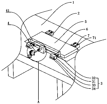
[0029] Embodiment 1: A kind of clamping device of heat exchanger, such as figure 1 As shown, it includes a base 1, a first clamping block 2 and a second clamping block 3 arranged in parallel on the base 1, the first clamping block 2 and the second clamping block 3 are all fixed on the base 1, the first clamping block The clamping block 2 and the second clamping block 3 can stably clamp the fin 5 when needed.

[0030] The second clamping block 3 includes a fixed part 31 and a sliding part 32, the fixed part 31 is fixed on the base 1, the sliding part 32 is located on the side of the fixed part 31 facing the first clamping block 2, the sliding part 32 and the fixed part 31 pass through The slide bar 33 is connected, and one end of the slide bar 33 is fixed to the sliding part 32, and the other end passes through the fixed part 31, and a stopper 34 extends from one end passing through the fixed part 31, on the slide bar 33 between the sliding part 32 and the fixed part 31 The sp...


PUM


Abstract

The invention discloses a clamping device of a heat exchanger. According to the technical scheme, the clamping device has the advantage of being capable of stably clamping fins and is characterized bycomprising a pushing mechanism; the pushing mechanism comprises a connecting rod, a conduction mechanism moving linearly in a reciprocating mode and a power mechanism providing power for the conduction mechanism; the connecting rod is connected with a plurality of sliding parts, and the pushing mechanism pushes the connecting rod to move linearly. The distance between the sliding parts and a fixed part is adjusted through the pushing mechanism to clamp fins, the power mechanism is started, power is provided for the conduction mechanism, and the conduction mechanism can push the connecting rod, so that the connecting rod drives the sliding parts to slide in the direction of the fins, and all the sliding parts synchronously clamp the fins at the same time.

Description

technical field [0001] The invention relates to the field of clamping devices, in particular to a clamping device for heat exchangers. Background technique [0002] The clamping device of the heat exchanger assembly machine is a clamping device when assembling the heat exchanger fins. [0003] At present, the Chinese patent with the publication number CN206230211U discloses a stacking device in a heat exchanger assembly machine, which includes a workbench, and the stacking device includes a fin guide plate, a flat tube guide plate and a positioning frame, and the fin guide plate The plate, the flat tube guide plate and the positioning frame are sequentially arranged on one end of the workbench, and the first passage for the fins to be placed vertically is formed between the fin guide plate and the flat tube guide plate, and the flat tube guide plate and the positioning frame A second channel is formed between the two to allow the flat tubes to be placed vertically. The work...

Claims


Application Information

Patent Timeline
IPC IPC(8): B25B11/02B23P19/00
CPCB23P19/00B25B11/02
Inventor 张磊
Owner WUXI TRS HEAT EXCHANGER CO LTD
Why Eureka
Try Eureka