Network switch with centralized wiring function for network communication

A network switch and network communication technology, applied in the direction of selection of devices, electrical components, etc., can solve the problems of inconvenient application, increased maintenance work intensity, scattered installation, etc., to ensure stability and firmness, improve firmness, and ensure installation safety Effect

Inactive Publication Date: 2021-04-09
吉铁磊
View PDF0 Cites 0 Cited by
  • Summary
  • Abstract
  • Description
  • Claims
  • Application Information

AI Technical Summary

Problems solved by technology

The traditional network switch does not centralize the connection lines, but installs them scatteredly. During the later maintenance, it is necessary to straighten the lines one by one, and then complete the maintenance. The intensity of the maintenance work is greatly increased, and the application is very inconvenient.

Method used


Image

  • Network switch with centralized wiring function for network communication
  • Network switch with centralized wiring function for network communication
  • Network switch with centralized wiring function for network communication

Examples


Embodiment 1

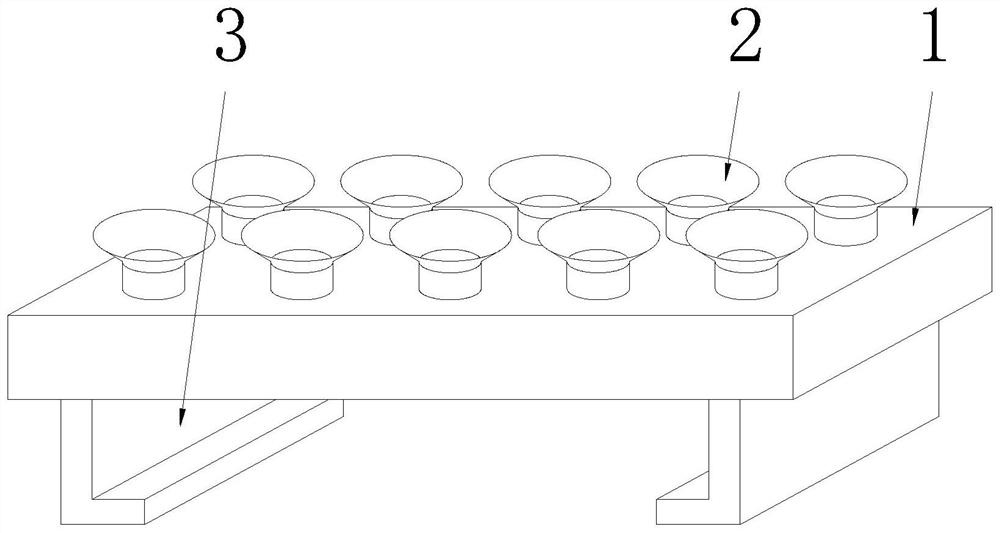
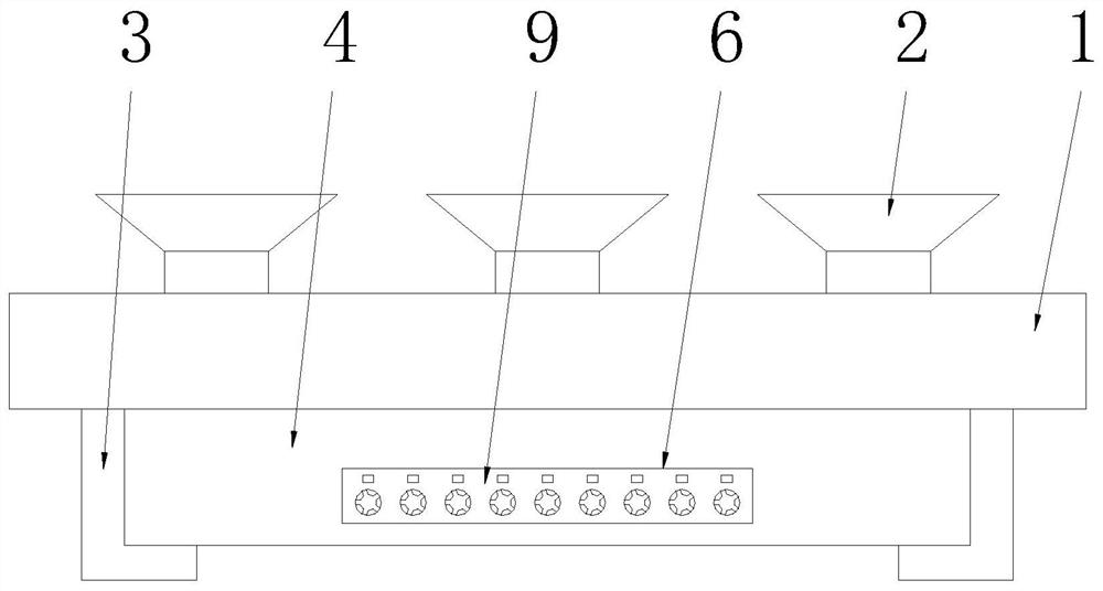
[0035] See Figure 1-5 , a network switch for network communication with a centralized wiring function, comprising a suspension box 1, a plurality of suction cups 2 are evenly provided on the top of the suspension box 1, brackets 3 are symmetrically provided on the left and right sides of the bottom end of the suspension box 1, A switch body 4 is arranged between the two brackets 3, and the bracket 3 can be suspended and suspended from the ceiling through the hanging box 1 and the suction cup 2, and then the switch body 4 is hoisted at a high altitude, so that the switch body 4 does not occupy the indoor ground Space, the network cable connected to it is not easy to be knocked off, which can greatly improve the convenience of the switch body application;

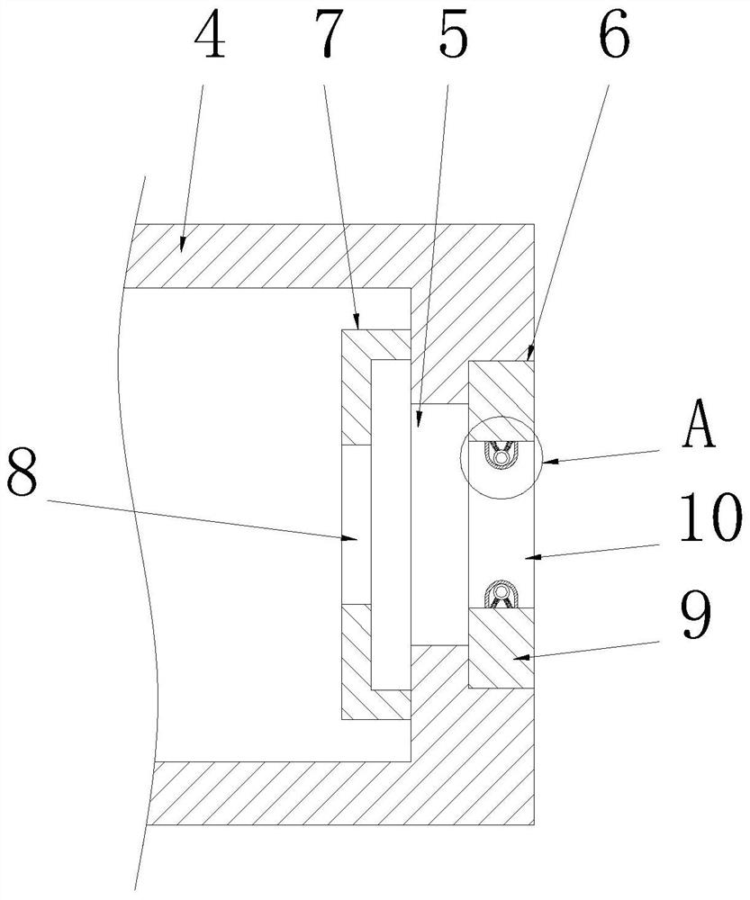
[0036] The front of the switch body 4 is provided with an inspection cavity 6, and a plurality of wiring holes 5 are uniformly connected on the inner cavity side wall of the inspection cavity 6. A fixed wire plate 9 is clamp...

Embodiment 2

[0040] See Figure 6-7 The difference from Embodiment 1 is that the bracket 38 includes a frame plate 31, the frame plate 31 is an L-shaped structure, and the adjacent end of the bottom wall of the frame plate 31 is symmetrically provided with a manipulation cavity 32, and the frame plate 31 A fastening cavity 33 is provided on the bottom wall of the inner cavity, and the fastening cavity 33 is connected to the control cavity 32 through a communication hole 34. The internal thread of the communication hole 34 is connected to a screw 35, and the top end of the screw 35 rotates through a bearing seat 37. A top plate 38 matching the fastening cavity 33 is connected, and the bottom end of the screw rod 35 is fixedly connected to the rotating handle 36. The axis of the screw rod 35 coincides with the axis of the rotating handle 36. Finally, by turning the turning handle 36 in the forward direction, the turning handle 36 drives the screw 35 to rotate up, and then the screw 35 pushes...

Embodiment 3

[0043] See Figure 8 The difference from Example 1 is that the top of the hanging box 1 is connected to the suction cup 2 through a number of suction holes 101, the suction cup 2 is made of silica gel, and one side of the hanging box 1 is connected to the main air pipe 102. One end of the main air pipe 102 away from the suspension box 1 is connected to a tee pipe 103, and the other two ends of the tee pipe 103 are respectively connected to an exhaust pipe 104 and an air supply pipe 107. The exhaust pipe 104 is equipped with One-way valve 105 and exhaust air bag 106, described exhaust air bag 106 is arranged on the right side of one-way valve 105, and control valve 108 is installed on described air supply pipe 107, when hanging box 1 cooperates suction cup 2 to carry out hoisting, close control Valve 108, and then through the exhaust air bag 106 and the exhaust pipe 104 to discharge the air in the inner cavity of the hanging box 1, a negative pressure can be formed in the inner...


PUM


Abstract

The present invention discloses a network switch with the centralized wiring function for network communication, which comprises a hanging box, a plurality of suction cups are evenly arranged at the top end of the hanging box, brackets are symmetrically arranged on the left side and the right side of the bottom end of the hanging box, and a switch body is arranged between the two brackets; an overhaul cavity is formed in the front surface of the switch body, a plurality of wiring holes are uniformly connected to the side wall of an inner cavity of the overhaul cavity in a penetrating manner, a fixed wire plate is clamped in the overhaul cavity, and a plurality of fixed wire holes matched with the wiring holes are uniformly formed in the fixed wire plate. During wiring, a connecting wire directly penetrates through the wire fixing hole and the wiring hole in sequence and can be connected to the inner cavity of the switch body; and then the connecting wire is firmly clamped in the wire fixing hole under the combined action of the top ring, the telescopic rod and the pre-tightening spring, so that the connection firmness of the connecting wire on the switch body is ensured; in addition, all connections are fixed on the fixed line board in a centralized manner, so that the convenience in later maintenance can be greatly improved.

Description

technical field [0001] The invention relates to the technical field of network switches, in particular to a network switch for network communication with a centralized wiring function. Background technique [0002] A network switch is a device for expanding the network, which can provide more connection ports in the sub-network to connect more computers. Broadly speaking, there are two types of switches: WAN switches and LAN switches. WAN switches are mainly used in the field of telecommunications to provide a basic communication platform. The LAN switch is used in the local area network to connect terminal devices, such as PCs and network printers. [0003] When the network switch is in use, many connecting wires are usually installed on it. Traditional network switches do not centrally handle the connection lines, but are installed in a scattered manner. During later maintenance, it is necessary to straighten the lines one by one before completing the maintenance. The m...

Claims


Application Information

Patent Timeline
IPC IPC(8): H04Q1/10H04Q1/14
CPCH04Q1/10H04Q1/14
Inventor 吉铁磊
Owner 吉铁磊
Why Eureka
Try Eureka