Semi-formed reinforcement cage overall die inlet structure

A technology of steel cages and steel bars, applied in structural elements, ceramic molding machines, building components, etc., can solve problems such as low work efficiency

Pending Publication Date: 2019-08-06
苏州良浦节能新材料股份有限公司
View PDF0 Cites 0 Cited by
  • Summary
  • Abstract
  • Description
  • Claims
  • Application Information

AI Technical Summary

Problems solved by technology

[0004] In view of this, the present invention provides a half-formed steel cage integral mold structure, aiming to solve the problem of low work efficiency caused by the fact that the semi-formed steel cage can only be positioned and in...

Method used


Image

  • Semi-formed reinforcement cage overall die inlet structure
  • Semi-formed reinforcement cage overall die inlet structure
  • Semi-formed reinforcement cage overall die inlet structure

Examples


Embodiment 1

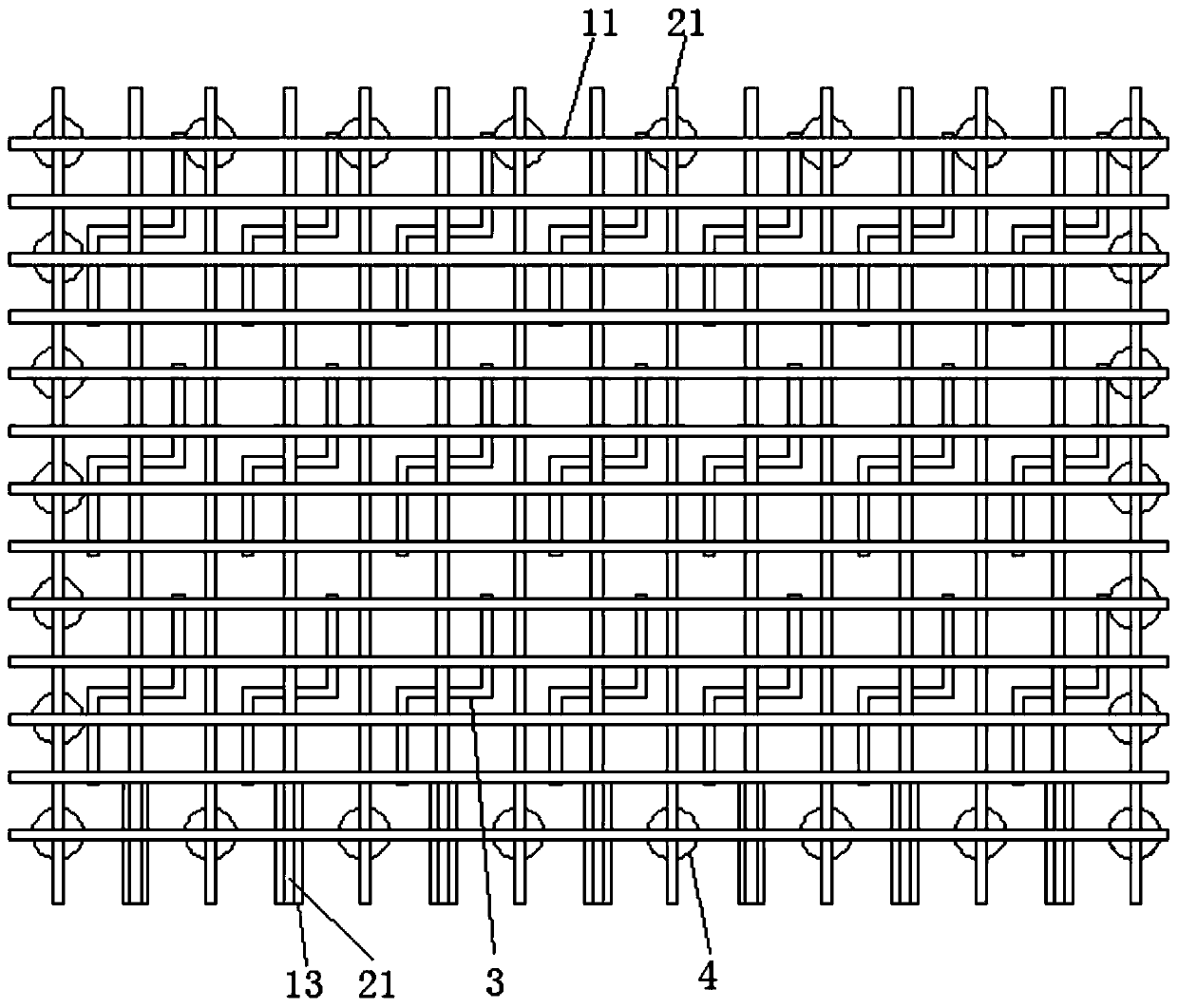
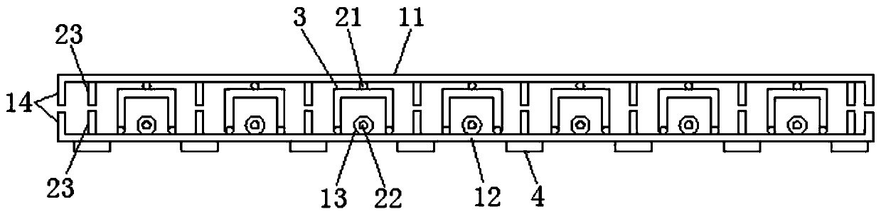
[0023] see Figure 1-2 , the figure shows a semi-formed reinforcement cage integral molding structure provided by Embodiment 1 of the present invention, which includes an outer reinforcement assembly, an inner reinforcement assembly, a support assembly and a positioning assembly, and the inner reinforcement assembly includes a first top set up and down The steel bar 11 and the first bottom steel bar 12, the first top steel bar 11 and the first bottom steel bar 12 are evenly arranged; the outer steel bar assembly includes the second top steel bar 21 and the second bottom steel bar 22 arranged up and down, and the first top steel bar 11 is located at The outside of the second top reinforcement bar 21, the first bottom reinforcement bar 12 is positioned at the outside of the second bottom reinforcement bar 22; The steel bars 22 are cross-connected to form the lower steel mesh; the support assembly includes a number of support frames 3 arranged between the upper steel mesh and the...

Embodiment 2

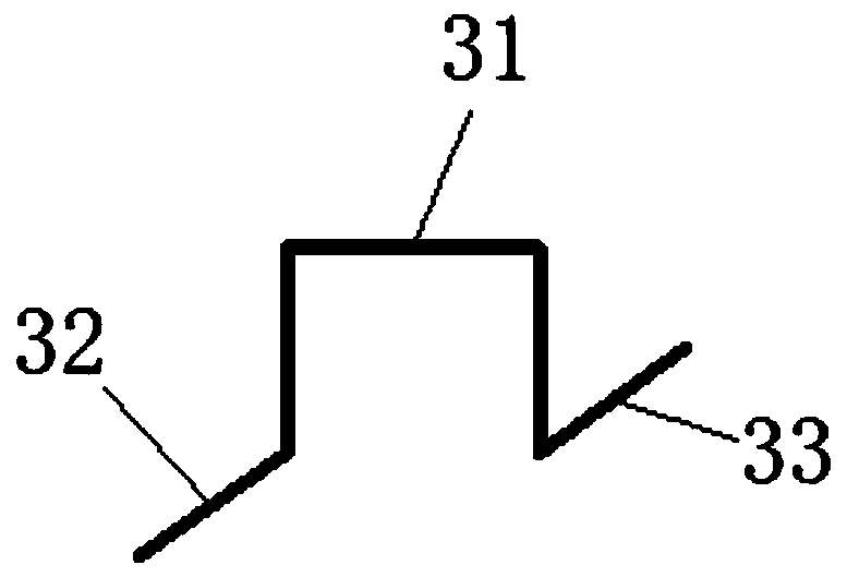
[0027] see image 3, the figure shows a semi-formed steel cage integral molded structure provided by Embodiment 2 of the present invention. On the basis of the above embodiments, this embodiment further makes the following technical solutions as improvements: support frame 3 Including the first support bar 31, the second support bar 32 and the third support bar 33, the first support bar 31 is in a "U" shape, the second support bar 32 and the third support bar 33 are arranged on both sides of the first support bar 31 free ends, and set in opposite directions; the support frame 3 is an integrally formed structure.

[0028] Through the above further improvements, this embodiment has the following advantages compared with the prior art: the setting of multiple support points and integrally formed structure improves the overall support force of the support frame 3 and also improves the connection strength of the reinforcement cage .

Embodiment 3

[0030] see Figure 4-6 , the figure shows a semi-formed reinforcement cage integral mold structure provided by Embodiment 3 of the present invention. On the basis of the above embodiments, this embodiment further makes the following technical solutions as improvements: positioning plate 4 Including the chassis 41 and the first positioning groove 42 and the second positioning groove 43 arranged on the chassis 41, the first positioning groove 42 and the second positioning groove 43 are vertically arranged, and the first positioning groove 42 is lower than the second positioning groove 43 The widths of the first positioning groove 42 and the second positioning groove 43 are larger than the outer diameters of the first bottom reinforcing bar 12 and the second bottom reinforcing bar 22 ;

[0031] Through the above-mentioned further improvement, this embodiment has the following advantages compared with the prior art: a positioning plate 4 can simultaneously position the first botto...


PUM


Abstract

The invention provides a semi-formed reinforcement cage overall die inlet structure which comprises an outer side steel bar assembly, an inner side steel bar assembly, a supporting assembly and a positioning assembly. The inner side steel bar assembly is located on the inner side of the outer side steel bar assembly. The inner side steel bar assembly comprises first top steel bars and first bottomsteel bars. The outer side steel bar assembly comprises second top steel bars and second bottom steel bars. The first top steel bars and the second top steel bars are connected in a crossed manner toform an upper steel bar net, and the first bottom steel bars and the second bottom steel bars are connected in a crossed manner to form a lower steel bar net. The supporting assembly comprises multiple supporting frames. The positioning assembly comprises multiple positioning discs which are located at the connecting positions of the outermost sides of the first bottom steel bars and the second bottom steel bars, and the positioning discs are located below the first bottom steel bars. By the adoption of the semi-formed reinforcement cage overall die inlet structure, manufacturing does not need to be conducted in a forming die, production can be conducted at any time, operation is convenient, time is saved, and the work efficiency is improved.

Description

technical field [0001] The invention relates to a structure of a concrete prefabricated part, in particular to an integral molded structure of a semi-formed reinforcement cage. Background technique [0002] PC is the English abbreviation of precast concrete (prefabricated concrete), which is called PC component in the field of housing industrialization. Such as prefabricated reinforced concrete column foundation, prefabricated steel structure steel column foundation, street lamp billboard column reinforced concrete foundation, prefabricated floor slab. Correspondingly, traditional cast-in-place concrete requires on-site molding, on-site pouring and on-site maintenance. Prefabricated concrete is widely used in construction, transportation, water conservancy and other fields, and plays an important role in the national economy. Especially for some municipal projects located in remote areas, which are not suitable for on-site pouring and forming, they are made into prefabrica...

Claims


Application Information

Patent Timeline
IPC IPC(8): B28B23/02E04C5/06
CPCB28B23/02B28B23/024E04C5/06E04C5/0627
Inventor 赵斌王丽明刘红兵张佳煜陈晋宇黄李园
Owner 苏州良浦节能新材料股份有限公司
Why Eureka
Try Eureka