Powerful double-pipeline brake cylinder

A technology of brake cylinder and dual pipelines, which is applied in the direction of brake cylinder, etc., can solve the problems of poor braking performance and small jacking force, and achieve the effects of long service life, improved braking force and reduced maintenance cost

Pending Publication Date: 2019-08-06
广西环江航舵汽车科技有限公司
View PDF6 Cites 0 Cited by
  • Summary
  • Abstract
  • Description
  • Claims
  • Application Information

AI Technical Summary

Problems solved by technology

[0003] The object of the present invention is to provide a brake cylinder to solve the existing technical problem of poor braking performance of the vehicle due to the low thrust of the brake cylinder in view of the above problems.

Method used


Image

  • Powerful double-pipeline brake cylinder
  • Powerful double-pipeline brake cylinder
  • Powerful double-pipeline brake cylinder

Examples


Embodiment 1

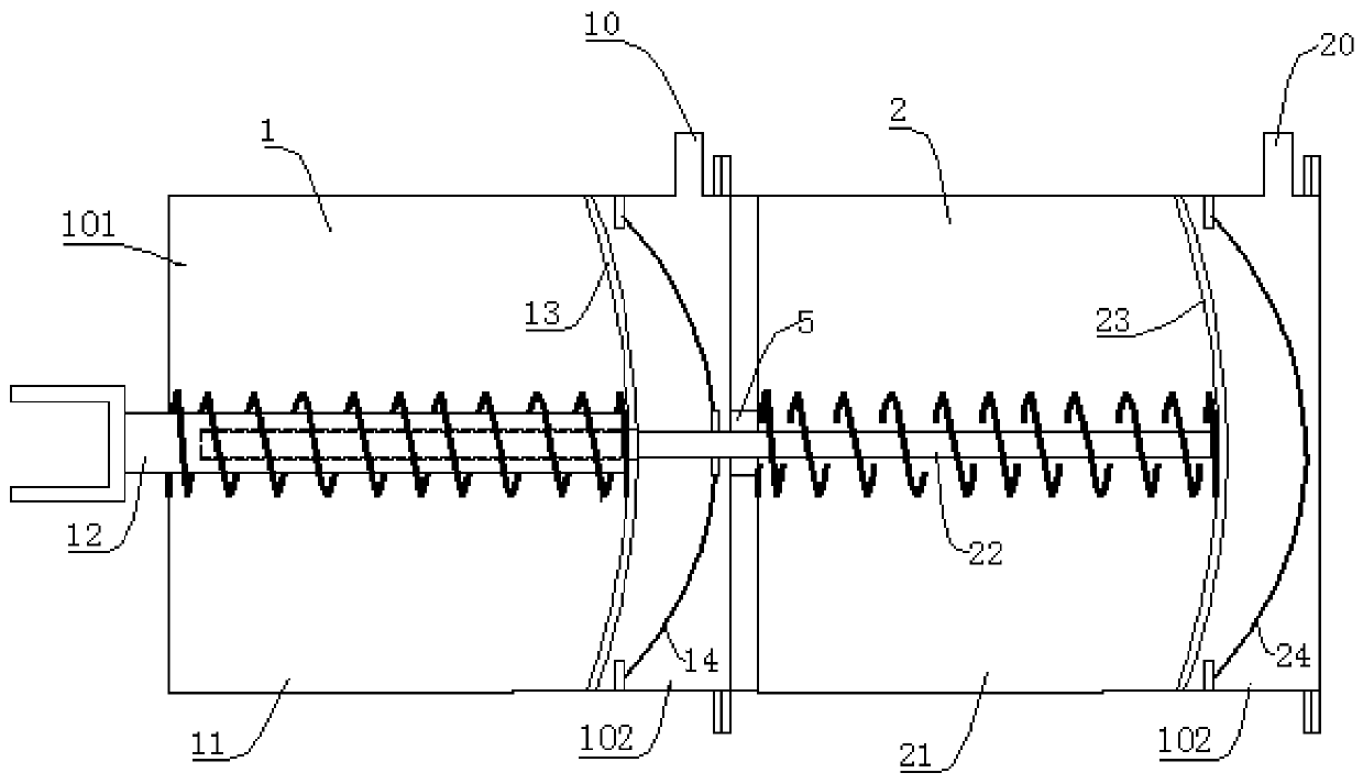
[0026] A powerful dual-pipeline brake cylinder, including an output pump 1 and a booster pump 2, the output pump 1 includes a first pump body 11, a first push rod 12 and a first piston 13, and the first piston 13 is located in the first pump body 11 Inside, the first push rod 12 is fixedly connected with the first piston 13; the booster pump 2 includes a second pump body 21, a second push rod 22 and a second piston 23, the second piston 23 is located in the second pump body 21, and the second The push rod 22 is fixedly connected with the second piston 23; the second pump body 21 is fixedly arranged at the rear part of the first pump body 11, and a through hole is provided between the first pump body 11 and the second pump body 21, and the second push rod 22 One end passes through the through hole and leans against the first push rod 12 .

Embodiment 2

[0028] Such as Figure 1 to Figure 4As shown, the structure of this embodiment is basically the same as that of Embodiment 1, the difference is that the output pump 1 and the booster pump 2 are both pneumatic brake pumps, and the output pump 1 includes a first pump body 11, a first push rod 12, a second A piston 13, a first rubber cup 14, and the first pump body 11 are provided with an inner chamber, and the first rubber cup 14 is arranged in the inner chamber, and the first rubber cup 14 divides the inner chamber into a piston chamber 101 and a blower chamber. cavity 102, the first piston 13 is slidably installed in the piston cavity 101, one end of the first push rod 12 extends into the piston cavity 101 and is fixedly connected with the first piston 13, and the other end of the first push rod 12 is located outside the first pump body 11 , the first piston 13 is laterally slidingly connected to the first pump body 11, the first pump body 11 is provided with a first air inlet...

Embodiment 3

[0035] Such as Figure 5 As shown, the structure of this embodiment is basically the same as that of Embodiment 1, the difference is that both the output pump 1 and the booster pump 2 are hydraulically driven brake pumps, the first piston 13 is slidingly connected with the first pump body 11, and the first piston The outer wall of 11 is provided with a first oil storage groove 71, the piston ring 9 is installed in the first oil storage groove 71, the rear part of the first pump body 11 is provided with a first oil inlet 81; the second piston 23 Slidingly connected with the second pump body 21, the outer wall of the second piston 23 is provided with a second oil storage groove 72, the piston ring 9 is installed in the second oil storage groove 72, and the rear part of the second pump body 21 is provided with There is a second oil inlet 82, and the brake pump of this structure is suitable for vehicles with hydraulically driven brakes.


PUM


Abstract

The invention provides a powerful double-pipeline brake cylinder which comprises an output pump and a reinforcement pump. The output pump comprises a first pump body, a first push rod and a first piston. The first piston is located in the first pump body. The first push rod is fixedly connected with the first piston. The reinforcement pump comprises a second pump body, a second push rod and a second piston. The second piston is located in the second pump body, and the second push rod is fixedly connected with the second piston. The second pump body is fixedly arranged on the rear portion of the first pump body, a through hole is formed between the first pump body and the second pump body, and one end of the second push rod penetrates through the through hole and abuts against the first push rod. The technical problem that the brake performance of a vehicle is poor due to the fact that the jacking force of an existing brake cylinder is small can be solved.

Description

technical field [0001] The invention relates to the technical field of auto parts, in particular to a powerful dual-pipeline brake cylinder. Background technique [0002] The brake cylinder is an indispensable chassis brake part of the brake system. Its main function is to push the brake pads, and the brake pads rub against the brake drum to reduce the speed of the vehicle and stop it. Trucks for transportation often have to run long-distance transportation, and the quality of the brake cylinder plays an important role in whether the long-distance transportation of trucks is smooth and safe. The brake cylinder of existing truck generally comprises pump body, is located at the air inlet above pump body, is enclosed within the film in pump body, is located at the piston in pump body, push rod and the return spring etc. that are enclosed within on push rod. The main disadvantages of the existing brake cylinders are that the film is easily damaged, and the braking effect is not...

Claims


Application Information

Patent Timeline
Patent Type & Authority Applications(China)
IPC IPC(8): B60T17/08
CPCB60T17/08
Inventor 梁芳文
Owner 广西环江航舵汽车科技有限公司
Why Eureka
Try Eureka