Damping closed type bridge expansion joint device

An expansion joint, closed technology, applied in the direction of bridges, bridge parts, bridge construction, etc., can solve the problems of lack of shock absorption and buffer performance, immature expansion joint technology, poor seismic performance of bridges, etc., to achieve convenient and smooth passage, avoid The effect of tearing or pulling damage, good shock absorption and cushioning properties

Pending Publication Date: 2019-08-06
刁望东
View PDF0 Cites 7 Cited by
  • Summary
  • Abstract
  • Description
  • Claims
  • Application Information

AI Technical Summary

Problems solved by technology

[0002] Bridge expansion joints are set to meet the requirements of bridge deck deformation. Usually, expansion joints are set between two girder ends, between girder ends and abutments, or at the hinged position of the bridge. The expansion joints are required to be parallel and perpendicular to the bridge axis. Two directions to ensure free expansion and contraction, solid and reliable, and no jumping when vehicles pass by, can prevent the infiltration of rainwater and garbage and sediment, and are easy to operate during installation, inspection, removal of dirt and maintenance, but the current bridge Expansion joint technology is not mature enough, using mid-buried waterstop to transfer, the installation process is complicated, assembly and maintenance are inconvenient; and the seismic performance of the bridge is poor, it does not have good shock absorption and buffer performance, the vibration is large, the noise is large, and the installation and maintenance are not easy. convenient

Method used


Image

  • Damping closed type bridge expansion joint device
  • Damping closed type bridge expansion joint device
  • Damping closed type bridge expansion joint device

Examples


Embodiment Construction

[0017] The following will clearly and completely describe the technical solutions in the embodiments of the present invention with reference to the accompanying drawings in the embodiments of the present invention. Obviously, the described embodiments are only some, not all, embodiments of the present invention. Based on the embodiments of the present invention, all other embodiments obtained by persons of ordinary skill in the art without making creative efforts belong to the protection scope of the present invention.

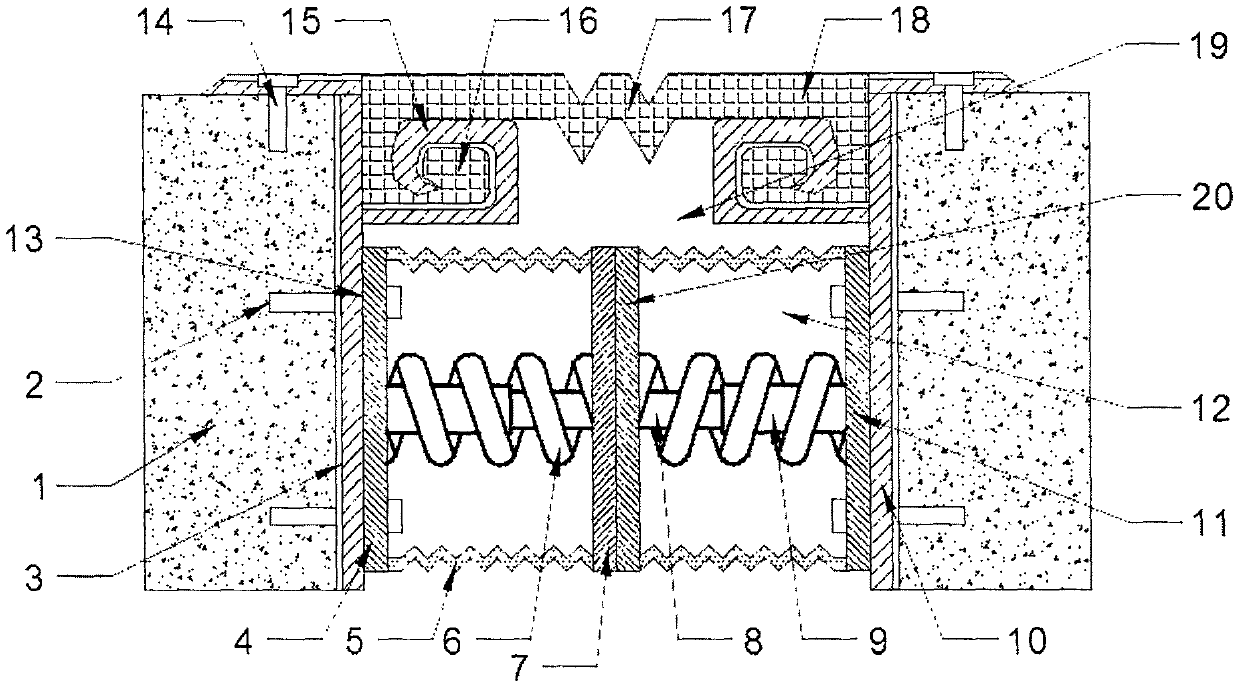
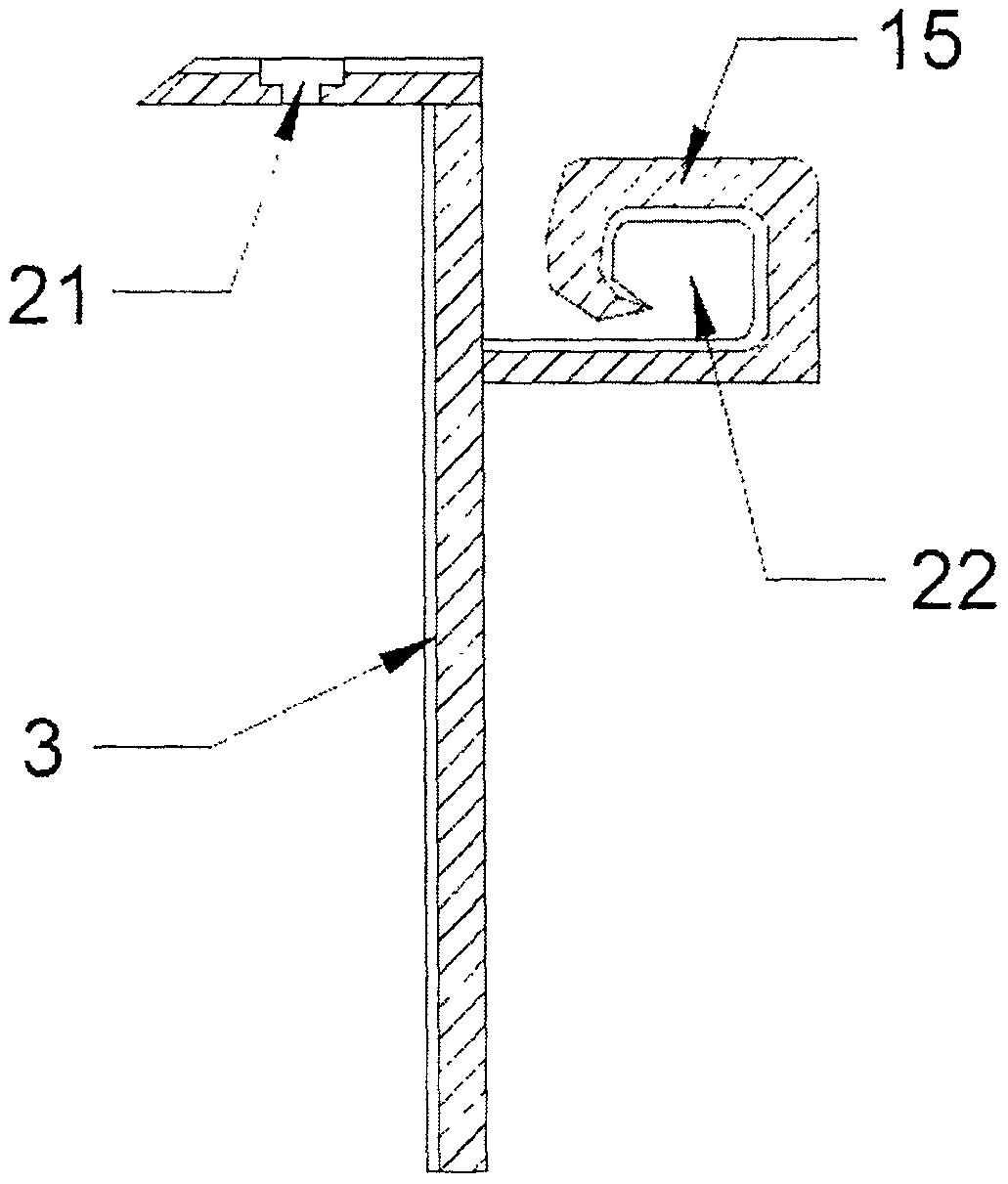
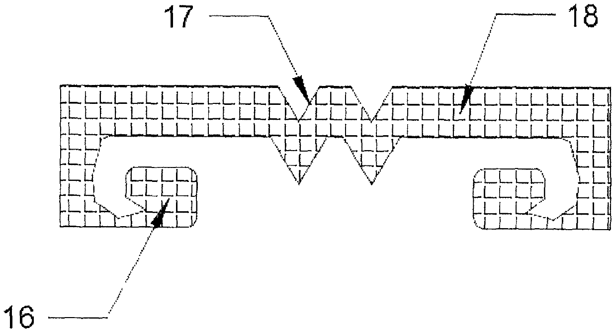
[0018] see Figure 1~4 , in an embodiment of the present invention, a shock-absorbing closed bridge expansion joint device includes a bridge body 1, an L-shaped supporting steel plate I 3, an L-shaped supporting steel plate II 10, an elastic shock absorber 13, a corner code 15 and a water stop belt 18, the middle part of the bridge body 1 is provided with an expansion joint 19, and the bridge body 1 on both sides of the expansion joint 19 is respectively fixed...


PUM


Abstract

The invention discloses a damping closed type bridge expansion joint device which comprises a bridge body, an L-shaped supporting steel plate I, an L-shaped supporting steel plate II, elastic dampers,corner braces and a water stop belt; an expansion joint is arranged in the middle of the bridge body, and the L-shaped supporting steel plate I and the L-shaped supporting steel plate II are fixed tothe portions, on two sides of the expansion joint, of the bridge body correspondingly; the corner braces are welded to the upper side of the L-shaped supporting steel plate I and the upper side of the L-shaped supporting steel plate II correspondingly, embedding grooves are defined in the corner braces, embedding blocks are embedded in the embedding grooves, and the embedding blocks are arrangedat two ends of the water stop belt. The elastic dampers are mounted on the bottom sides of the L-shaped supporting steel plate I and the L-shaped supporting steel plate II; a traditional embedded assembly is replaced by the embedded assembly, the operation is convenient and fast, and the maintenance is easy; the telescopic section on the water stop belt is used for telescopic change of the lengthof the water stop belt, so tearing or traction damage of the water stop belt are avoided, and vehicles can pass through the water stop belt stably; the damping closed type bridge expansion joint device is good in buffering performance, the protection performance of which on a bridge is good, vibration is small, noise is low, and installation and maintenance are convenient.

Description

technical field [0001] The invention relates to the field of bridge engineering, in particular to a shock-absorbing closed bridge expansion joint device. Background technique [0002] Bridge expansion joints are set to meet the requirements of bridge deck deformation. Usually, expansion joints are set between two girder ends, between girder ends and abutments, or at the hinged position of the bridge. The expansion joints are required to be parallel and perpendicular to the bridge axis. Two directions to ensure free expansion and contraction, solid and reliable, and no jumping when vehicles pass by, can prevent the infiltration of rainwater and garbage and sediment, and are easy to operate during installation, inspection, removal of dirt and maintenance, but the current bridge Expansion joint technology is not mature enough, using mid-buried waterstop to transfer, the installation process is complicated, assembly and maintenance are inconvenient; and the seismic performance o...

Claims


Application Information

Patent Timeline
Patent Type & Authority Applications(China)
IPC IPC(8): E01D19/06
CPCE01D19/06
Inventor 刁望东
Owner 刁望东
Why Eureka
Try Eureka