Building wall body quick pouring device and method
A fast technology for building walls, applied in the direction of buildings, building components, building structures, etc., can solve the problems of high manpower consumption, difference between pouring time and slurry amount, affecting the quality of building walls, etc. less, high applicability, uniform effect of pouring construction slurry
- Summary
- Abstract
- Description
- Claims
- Application Information
AI Technical Summary
Problems solved by technology
Method used
Image
Examples
specific Embodiment approach 1
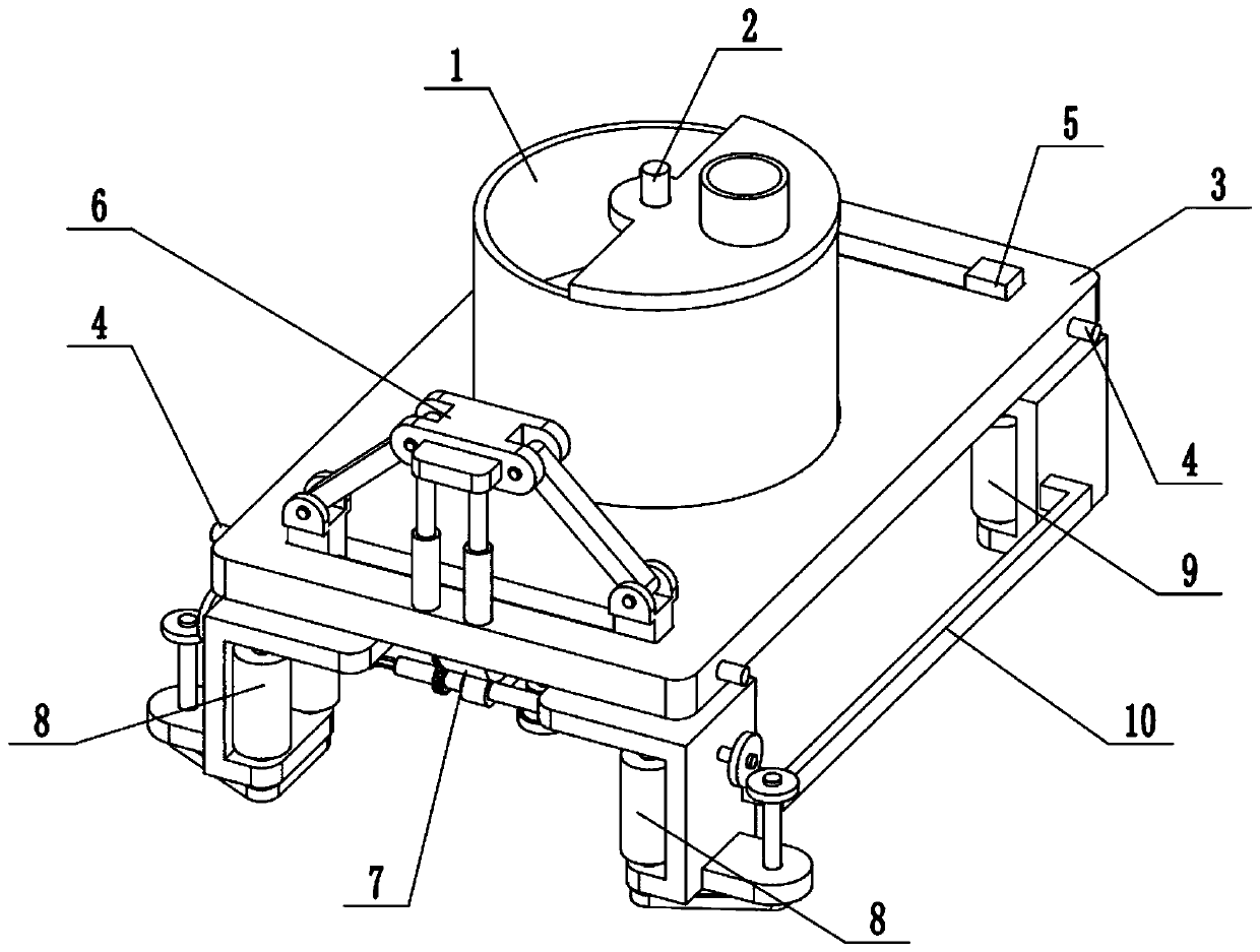
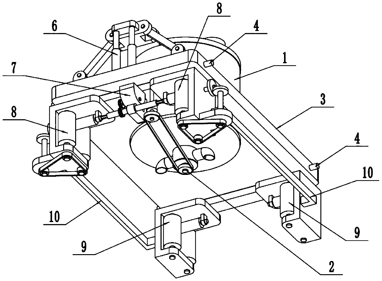
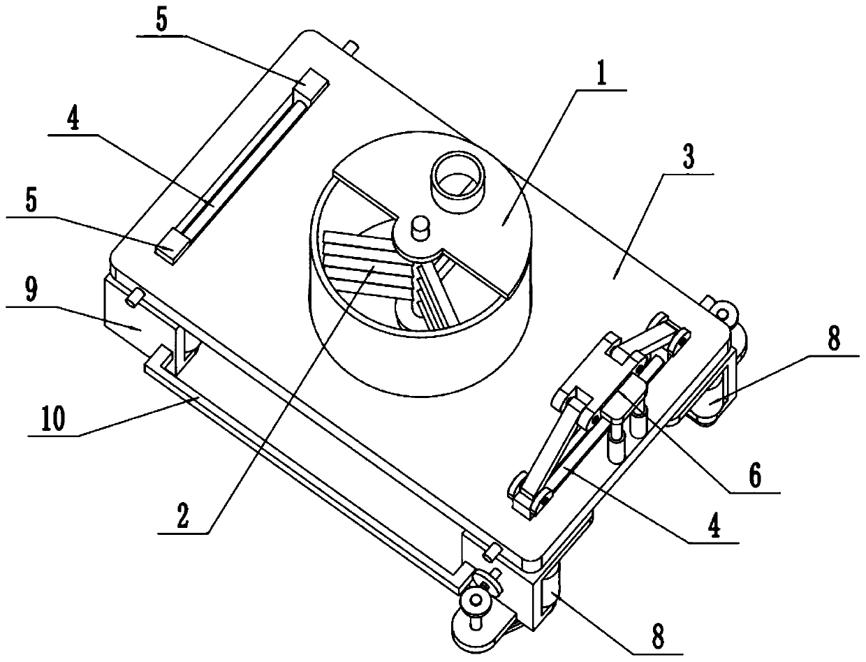
[0036] Such as Figure 1-13 As shown, a rapid pouring device for building walls includes a pouring cylinder 1, a stirring and conveying mechanism 2, a horizontal frame 3, a guide shaft 4, a guide slider 5, a distance adjustment mechanism 6, a drive control mechanism 7, and an active walking mechanism 8. The passive walking mechanism 9 and the first linkage frame 10, the pouring cylinder 1 is fixedly connected in the circular through hole in the center of the horizontal frame 3; The top surface and the bottom surface of the cylinder 1; the horizontal frame 3 is provided with two front and rear rectangular chutes, and the inner sides of the two rectangular chutes are respectively fixedly connected with a guide shaft 4; one end of the distance adjustment mechanism 6 is slidably fitted Connected to a guide shaft 4, the distance adjustment mechanism 6 is slidably connected to a rectangular chute, and the other end of the distance adjustment mechanism 6 is fixedly connected to the h...
specific Embodiment approach 2
[0038] Such as Figure 1-13 As shown, the casting cylinder 1 includes a feed pipe 1-1, a cylinder cover 1-2, a cylinder body 1-3, a material control pipe 1-4 and a pouring pipe 1-5; the feed pipe 1-1 is fixed Connected in the feeding port of the cylinder cover 1-2, the semicircular cylinder cover 1-2, the cylinder body 1-3 and the material control pipe 1-4 are fixedly connected from top to bottom; the material control pipe 1-4 The two sides of each are fixedly connected and communicated with a pouring pipe 1-5 respectively. The inside of the pouring cylinder 1 is used to inject the slurry used for pouring the building wall, and the feed pipe 1-1 at the upper end of the pouring cylinder 1 passes through the telescopic hose with the slurry pump and the slurry stored with the slurry. The tank is connected, and the slurry to be poured is injected into the pouring cylinder 1 through the telescopic hose with the slurry pump; the slurry can enter the two pouring pipes through the co...
specific Embodiment approach 3
[0042] Such as Figure 1-13 As shown, the distance adjustment mechanism 6 includes an electric push rod 6-1, a lifting seat 6-2, a push-pull connecting rod 6-3 and a distance adjustment slider 6-4; the electric push rod 6-1 is provided with two , the fixed ends of the two electric push rods 6-1 are all fixedly connected on the top surface of the horizontal frame 3, and the movable ends of the two electric push rods 6-1 are all fixedly connected on the lifting base 6-2; The two ends of seat 6-2 are respectively rotated and matched to connect the inner end of a push-pull connecting rod 6-3, and the outer ends of two push-pull connecting rods 6-3 are respectively rotated to connect a distance-adjusting slider 6-4, and two distance-adjusting sliders Block 6-4 is symmetrically slidably connected to a guide shaft 4, and two distance-adjustable sliders 6-4 are symmetrically slidably connected in a rectangular chute; the lower ends of the two distance-adjustable sliders 6-4 are respec...
PUM
 Abstract
Description
Claims
Application Information
 - R&D
- Intellectual Property
- Life Sciences
- Materials
- Tech Scout
- Unparalleled Data Quality
- Higher Quality Content
- 60% Fewer Hallucinations
Browse by: Latest US Patents, China's latest patents, Technical Efficacy Thesaurus, Application Domain, Technology Topic, Popular Technical Reports.
© 2025 PatSnap. All rights reserved.Legal|Privacy policy|Modern Slavery Act Transparency Statement|Sitemap|About US| Contact US: help@patsnap.com


