A rotor temperature measurement and simulation system and method for a low-temperature centrifugal fluid machine

A technology of fluid machinery and rotor temperature, which is applied in low-temperature temperature measurement, temperature measurement of moving solids, thermometers, etc., can solve the problem of inability to measure rotor temperature, and achieve the effect that is beneficial to the design of thermal insulation structure

Active Publication Date: 2020-12-11
ZHEJIANG UNIV
View PDF3 Cites 0 Cited by
  • Summary
  • Abstract
  • Description
  • Claims
  • Application Information

AI Technical Summary

Problems solved by technology

[0004] Aiming at the above problems, the present invention proposes a rotor temperature measurement simulation system and method of a low-temperature centrifugal fluid machine, which solves the problem that the rotor temperature cannot be measured at low temperature

Method used


Image

  • A rotor temperature measurement and simulation system and method for a low-temperature centrifugal fluid machine
  • A rotor temperature measurement and simulation system and method for a low-temperature centrifugal fluid machine

Examples


Embodiment 1

[0049] Example 1 Test the influence of inlet medium temperature on fluid machine 2 rotor temperature

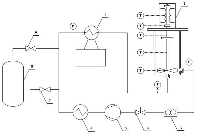
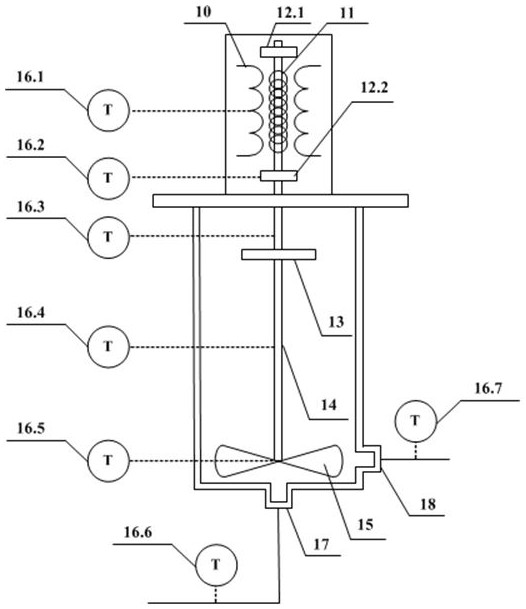
[0050] Turn on the power fluid machine 5 and the refrigerator 1, and the system starts to cool down. When the cooling capacity provided by the refrigerator 1 is balanced with the leakage heat of the system, the temperature at the inlet temperature measuring point 16.6 drops to the lowest value, and the rotor temperature is measured. Keep the electric power of the stator electric heating wire 10, the rotor electric heating wire 11, the upper rotor bearing 12.1 and the lower rotor bearing 12.2 electric heating sheet constant, turn on the heater 6, and set the heating power. Due to the increase of the heat load of the system, the temperature of the inlet temperature measuring point 16.6 will rise at this time, and it will stabilize after a period of time, and the rotor temperature will be measured again. Change the heating power of heater 6 afterwards, carry out the test of same...

Embodiment 2

[0051] Embodiment 2 Test the influence of the heat generated inside the motor on the temperature of the fluid machine 2 rotor

[0052] Adjust the electric heating power of the stator electric heating wire 10, the rotor electric heating wire 11, the upper rotor bearing 12.1 and the lower rotor bearing 12.2 electric heating sheet to the maximum value, turn on the power fluid machine 5 and the refrigerator 1, and the system starts to cool down. When the cooling capacity provided by machine 1 is in balance with the leakage heat of the system, the temperature at the inlet temperature measuring point 16.6 drops to the lowest value, and the rotor temperature is measured. Afterwards, reduce the power of the heating wire and heating plate in the motor, and reduce the thermal load of the system, so the temperature at the inlet temperature measuring point 16.6 will be further reduced, but to control the variable, that is, to keep the temperature at the inlet temperature measuring point 16...

Embodiment 3

[0053] Example 3 Test the influence of heat sink position on fluid machine 2 rotor temperature

[0054] Turn on the power fluid machine 5 and the refrigerator 1, and the system starts to cool down. When the cooling capacity provided by the refrigerator 1 is balanced with the leakage heat of the system, the temperature at the inlet temperature measuring point 16.6 drops to the lowest value, and the rotor temperature is measured. Maintain the electric power of the stator electric heating wire 10, the rotor electric heating wire 11, the upper rotor bearing 12.1 and the lower rotor bearing 12.2 electric heating sheet to keep constant, and change the axial position of the heat sink 13. At this time, the temperature distribution in the axial direction of the rotor changes. , the heat load of the system also changes accordingly, and the temperature at the inlet temperature measuring point 16.6 will also be slightly different. Adjust the heating power of the heater 6 to keep the temper...


PUM


Abstract

The invention discloses a rotor temperature measurement and simulation system and method of a low-temperature centrifugal fluid machine. The system includes a refrigerator, a centrifugal fluid machine to be tested, a flow meter, a flow regulating valve, a power fluid machine, and a heater, which are connected through pipelines. In the present invention, the refrigerating machine is used as a cold source, the power fluid machine provides circulating power for the medium in the system, and the rotor of the centrifugal fluid machine to be tested remains stationary. The system can realize the rotor temperature measurement of centrifugal fluid machinery when transporting low-temperature working fluid, obtain a complete internal temperature field and axial heat leakage, and help the design of the thermal insulation structure of the whole machine.

Description

technical field [0001] The invention relates to the technical field of rotor temperature measurement of fluid machinery, in particular to a rotor temperature measurement simulation system and method of low-temperature centrifugal fluid machinery. Background technique [0002] With the continuous development of cryogenic engineering, cryogenic centrifugal fluid machinery has been widely used in air separation, aerospace fields and helium cryogenic systems of large scientific projects, including liquid oxygen pumps in the 90K temperature zone and liquid nitrogen pumps in the 77K temperature zone , 40K temperature zone helium circulation fan, 20K temperature zone liquid hydrogen pump and 4K temperature zone helium cooling compressor, etc. The main difference between cryogenic fluid machinery and normal temperature fluid machinery is that cryogenic fluid machinery has very high requirements on thermal insulation performance, because the impeller side of the rotor is in a low tem...

Claims


Application Information

Patent Timeline
Patent Type & Authority Patents(China)
IPC IPC(8): G01K13/00G01K13/08
CPCG01K13/006G01K13/08
Inventor 孙大明苏峙岳
Owner ZHEJIANG UNIV
Why Eureka
Try Eureka