Apparatus for thermal characterization under non-uniform heat load

a technology of non-uniform heat load and apparatus, applied in the field of character, can solve the problems of affecting the thermal performance of the cooling device, affecting the cooling device and the cooling package, and affecting the cooling ability of the heat pipe, etc., and achieves the effect of improving the temperature measurement and increasing the emissivity of the cooling devi

Inactive Publication Date: 2008-09-04
GLOBALFOUNDRIES INC
View PDF102 Cites 5 Cited by
  • Summary
  • Abstract
  • Description
  • Claims
  • Application Information

AI Technical Summary

Benefits of technology

[0014]Briefly, in accordance with the present invention, disclosed is a method and apparatus for application of a non-uniform heat load to a cooling device, as well as a measurement and characterization of the thermal performance of: (i) the cooling device only; (ii) the complete cooling device package (i.e. cooling device, thermally conductive interface and chip); and (iii) the thermal conductive interface only. The inventive method and apparatus do not require physical coupling of measurement equipment to the device under test and, therefore, provide many benefits over the use of resistance heaters for power applications, thermocouples, and IR thermal imaging for temperature measurement. The method and device disclosed herein will also allow for rapid variation of hot spot or high power density locations on the device under test.
[0020]In yet another embodiment, the cooling device is coated with a blackbody coating to help absorb the laser beam and increase the emissivity of the cooling device, which improves the temperature measurements. In other embodiments, the test chip is coated with the blackbody coating. In still other embodiments, a layer of the blackbody coating is placed between the test chip and the cooling device in order to measure the thermally conductive interface between the chip and cooling device.

Problems solved by technology

Almost all the electrical energy consumed by the chip package is released into the surroundings as heat, which thus places an enormous burden on the cooling device and cooling package.
This phenomenon can adversely affect the thermal performance of the cooling device, which is typically designed to function and tested under a more spatially uniform heat load.
Specifically, degradation in cooling ability of the heat pipe 110 occurs at areas of high power density within the device.
Thus, when employing a heat pipe or a vapor chamber to cool a microprocessor or an electronic device, if there is a large non-uniformity in the power density of the chip, the boiling and / or evaporation in the evaporator region over the chip and interface will also be non-uniform.

Method used


Image

  • Apparatus for thermal characterization under non-uniform heat load
  • Apparatus for thermal characterization under non-uniform heat load
  • Apparatus for thermal characterization under non-uniform heat load

Examples


Embodiment Construction

[0038]It should be understood that these embodiments are only examples of the many advantageous uses of the innovative teachings herein. In general, statements made in the specification of the present application do not necessarily limit any of the various claimed inventions. Moreover, some statements may apply to some inventive features but not to others. In general, unless otherwise indicated, singular elements may be in the plural and vice versa with no loss of generality. In the drawings, like numerals refer to like parts through several views.

[0039]While the specification concludes with claims defining the features of the invention that are regarded as novel, it is believed that the invention will be better understood from a consideration of the following description in conjunction with the drawing figures, in which like reference numerals are carried forward.

[0040]Electronic Device

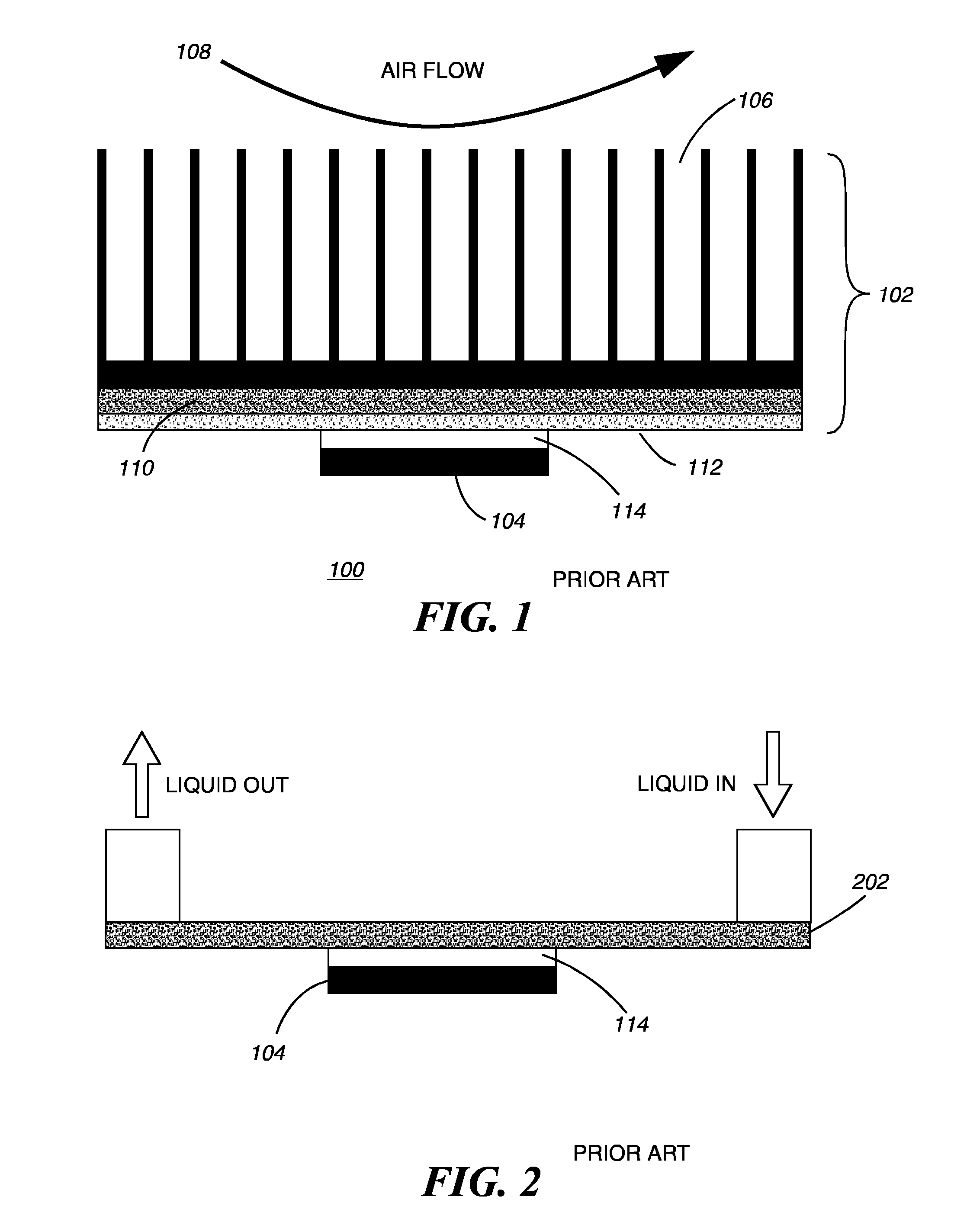
[0041]FIG. 7 shows a prior art electronic device 104 (previously shown in FIG. 1), having a top s...


PUM

PropertyMeasurementUnit
temperaturesaaaaaaaaaa

Abstract

A method and apparatus for real-time thermal characterization of a fully operating cooling device (1002). A heat source (1004) is applied to one or more areas on a cooling device (1002) to produce non-uniform heating of the cooling device. Infrared (IR) temperature imaging (1006) detects and measures the thermal distribution of the heat source (1004) on the cooling device (1002) to develop a thermal characterization of the cooling device (1002).

Description

CROSS-REFERENCE TO RELATED APPLICATIONS[0001]This application is based upon and claims priority from prior U.S. patent application Ser. No. 10 / 982,575, filed on Nov. 5, 2004, now U.S. patent Ser. No. ______, the entire disclosure of which is herein incorporated by reference in its entirety.BACKGROUND OF THE INVENTION[0002]1. Field of the Invention[0003]This invention relates in general to characterizing cooling devices and cooling packages for electronic components and more particularly, to an apparatus and method of thermal characterization of a cooling device under non-uniform heat loads.[0004]2. Description of the Related Art[0005]Microprocessor performance has improved significantly over the last decade. To effect this improvement in device performance, the density of circuitry has increased. More and more transistors are fabricated in smaller chip size. This has in turn, led to an exponential rise in package power densities, and this trend is expected to continue into the fores...

Claims


Application Information

Patent Timeline
Patent Type & Authority Applications(United States)
IPC IPC(8): G01K17/10
CPCH01L23/34H01L2924/0002H01L2924/00
Inventor HAMANN, HENDRIK F.IYENGAR, MADHUSUDAN K.LACEY, JAMES A.SCHMIDT, ROGER R.
Owner GLOBALFOUNDRIES INC
Why Eureka
Try Eureka