Toll collection system and toll collection method of vehicle on high-speed traffic road

A technology of road vehicles and toll collection systems, applied in the field of high-speed traffic road vehicle toll collection systems, can solve problems such as traffic safety hazards and damage to the order of highway toll collection, and achieve the goal of reducing adverse effects, avoiding traffic congestion and traffic accidents, and reducing erroneous actions Effect

Inactive Publication Date: 2019-08-06
NORTHEAST FORESTRY UNIVERSITY
View PDF4 Cites 7 Cited by
  • Summary
  • Abstract
  • Description
  • Claims
  • Application Information

AI Technical Summary

Problems solved by technology

These phenomena have not only seriously damaged the expressway toll order, but also caused great traffic safety hazards. In order to build a harmonious traffic, it is urgent to make reasonable improvements to the existing ETC

Method used


Image

  • Toll collection system and toll collection method of vehicle on high-speed traffic road

Examples


Embodiment 1

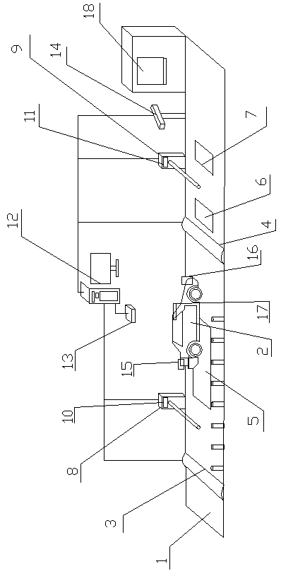
[0028] A high-speed traffic road vehicle toll collection system, its composition includes: ETC lane 1 and passing vehicle 2, described ETC lane is provided with pressure sensor A3, pressure sensor B4, weighbridge 5, entering the station RFID6, leaving the station RFID7, in manual Toll station 18 is provided with railing A8 and railing B9 respectively at a distance of 20m and 5m, and the weighbridge is arranged between the pressure sensor A and the pressure sensor B, and the ultrasonic module A10 is installed on the railing A , the ultrasonic module B11 is installed on the railing B, the pressure sensor A is connected with the ultrasonic module A and the host computer 12 respectively, and the host is respectively connected with the zigbee main module 13, the camera 14, the The ultrasonic module B is connected to the pressure sensor B, the distance between the inbound RFID and the outbound RFID and the pull bar B is 3m, and the railing A and the railing B are high-speed railings ...

Embodiment 2

[0030] According to the high-speed traffic road vehicle charging system described in embodiment 1, ID card A15 and ID card B16 are respectively installed on the rear license plate and the front license plate of the described passing vehicle, and the vehicle-mounted zigbee submodule 17 is installed in the described traveling vehicle , the vehicle-mounted zigbee sub-module transmits information wirelessly to the described zigbee main module, and the described zigbee main module feeds back the toll station information to the described vehicle-mounted zifbee sub-module, and stores it in the vehicle-mounted data memory .

Embodiment 3

[0032] According to the high-speed traffic road vehicle charging system described in embodiment 1 or 2, the host computer mainly provides user registration, recharging, system deduction, and processes vehicle information transmitted by Zigbee and RFID, and then feeds back signals to control railings and cameras .


PUM


Abstract

The invention relates to a toll collection system and toll collection method of vehicle on a high-speed traffic road. At present, the ETC systems are built actively in the country; but some disharmonious phenomena like entrance by mistake, toll avoidance by following, and toll avoidance by marking a small mark on a large vehicle occur at the early stage of development. The system comprises an ETClane (1) and a passing vehicle (2). A pressure sensor A (3), a pressure sensor B (4), a weighbridge (5), an entrance RFID (6), and an exit RFID (7) are arranged on the ETC lane; a railing A (8) and arailing B (9) are arranged at positions at distances to a manual toll station (18) of 20m and 5m respectively; the weighbridge is arranged between the s pressure sensor A and the pressure sensor B; anultrasonic module A (10) is installed on the railing A and an ultrasonic module B (11) is mounted on the railing B; and the pressure sensor A is connected to the ultrasonic module A and an upper computer 912. The toll collection system and toll collection method can be applied to the fields of vehicles and transportation.

Description

[0001] Technical field: [0002] The invention relates to a high-speed traffic road vehicle charging system and a charging method. [0003] Background technique: [0004] At present, my country is actively building an electronic toll collection system (ETC), but some disharmonious phenomena have appeared in the early stage of development, such as: "wrong entry", "following the car to evade the fare", "big cars and small bids evading the fare", etc. . [0005] The electronic toll collection system (also known as Electronic Toll Collection, referred to as ETC) has the advantages of charging without parking, fast speed, and no cash payment. It is an effective way to solve the congestion of expressway toll stations [1]. In my country, ETC is in a stage of vigorous development, and many provinces are actively building new ETC lanes. However, the penetration rate of ETC users in my country is only 3%, which shows that ETC is still in the early stage of promotion in most areas of my ...

Claims


Application Information

Patent Timeline
IPC IPC(8): G07B15/06G01G19/03
CPCG01G19/03G07B15/06G07B15/063
Inventor 王宪彬张雪常铮刘丹丹
Owner NORTHEAST FORESTRY UNIVERSITY
Why Eureka
Try Eureka