Magnetic power sliding rail device and intelligent terminal

A technology of magnetic power and slide rails, which is applied in the direction of telephone structure, telephone communication, electrical components, etc., can solve the problems of high motor cost, large occupied space, and poor experience, and achieve low production cost, small occupied space, and easy to use long life effect

Active Publication Date: 2019-08-06
SHENZHEN TRANSSION HLDG CO LTD
View PDF8 Cites 5 Cited by
  • Summary
  • Abstract
  • Description
  • Claims
  • Application Information

AI Technical Summary

Problems solved by technology

[0008]1. When the unpowered slide rail is designed in the mobile phone, the structure is simple, the space occupied is small, and the slide cover mobile phone can be made the thinnest, but the unpowered slide rail The slider mobile phone feels poor when sliding, there is no locking force to keep the slide rail open or closed, the slide rail is easy to loose, and the experience is poor
[0009]2. The motor-driven slide rail needs to design a special motor to drive the slide rail. higher cost
[0012] But the existing magnetic power slide rail scheme has its disadvantages, please refer to the attached Figure 1, the scheme of the magnetic power slide rail in the prior art adopts the principle of mutual exclusion in the thickness direction to drive, the driving force and the sliding direction Not completely parallel, which causes the loss of driving force, so the volume of the magnet is also required to be larger, and because there is always a mutually repulsive force in the thickness direction, the sliding feel is not very ideal

Method used


Image

  • Magnetic power sliding rail device and intelligent terminal
  • Magnetic power sliding rail device and intelligent terminal
  • Magnetic power sliding rail device and intelligent terminal

Examples


Embodiment Construction

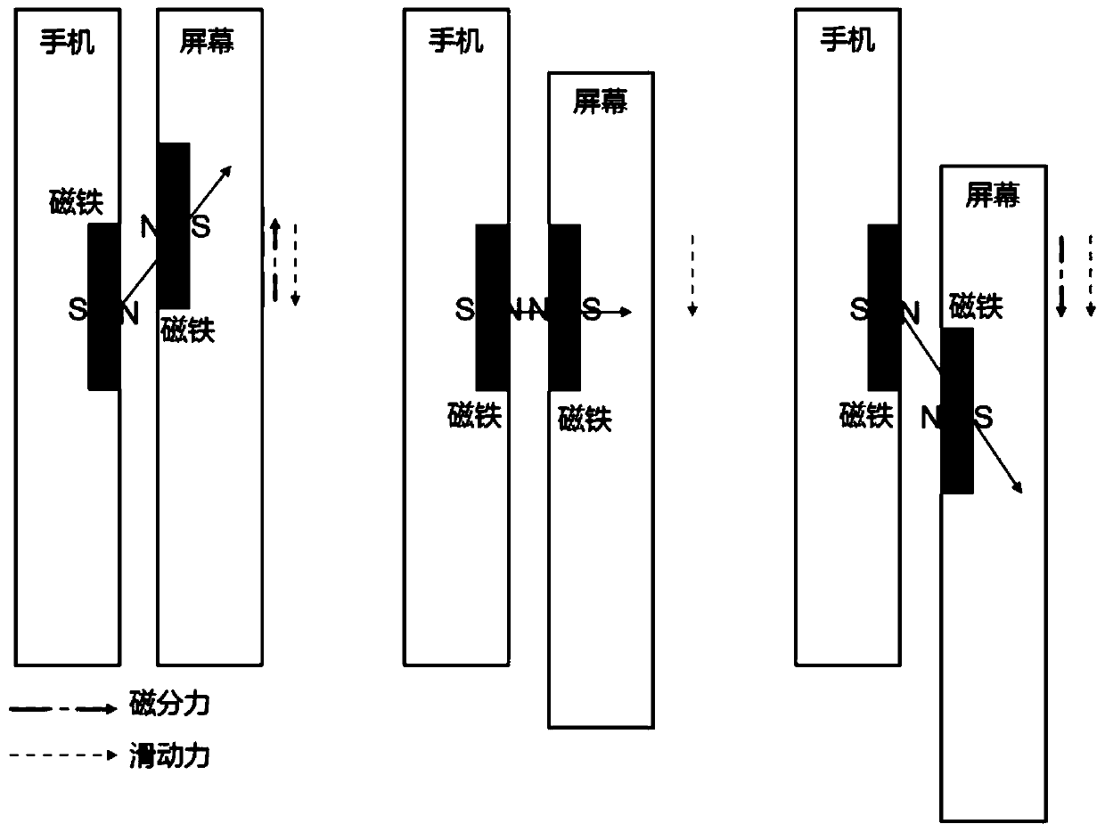
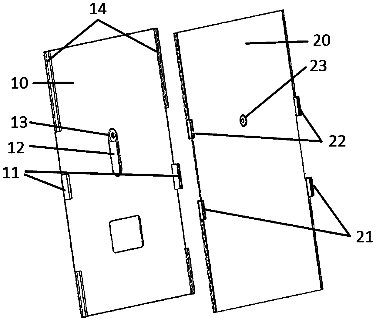
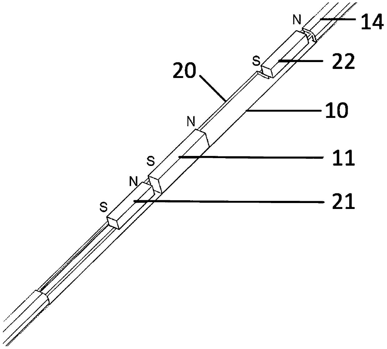
[0054] The advantages of the present invention will be further elaborated below in conjunction with the accompanying drawings and specific embodiments.

[0055] Reference will now be made in detail to the exemplary embodiments, examples of which are illustrated in the accompanying drawings. When the following description refers to the accompanying drawings, the same numerals in different drawings refer to the same or similar elements unless otherwise indicated. The implementations described in the following exemplary examples do not represent all implementations consistent with the present disclosure. Rather, they are merely examples of apparatuses and methods consistent with aspects of the present disclosure as recited in the appended claims.

[0056]The terminology used in the present disclosure is for the purpose of describing particular embodiments only, and is not intended to limit the present disclosure. As used in this disclosure and the appended claims, the singular ...


PUM


Abstract

The invention provides a magnetic power sliding rail device, which comprises a first sliding part and a second sliding part, wherein the first sliding part is provided with a first magnetic part; thesecond sliding part is provided with a second magnetic part and a third magnetic part; the first magnetic part is used for sliding towards the second magnetic part or the third magnetic part, and thefirst sliding part and the second sliding part are located at different opposite positions under the action of a magnetic force when the first magnetic part is located at a position close to the second magnetic part or the third magnetic part. The invention further provides an intelligent terminal with the sliding rail device. The magnetic power sliding rail device does not have driving force lossand good in sliding hand feeling.

Description

technical field [0001] The invention relates to the technical field of intelligent terminals, in particular to a magnetic power slide rail device and an intelligent terminal. Background technique [0002] As a guiding mechanism, slide rails are widely used in some equipment and products with guide devices, especially slide-type intelligent terminals, such as slide-type mobile phones. The differences can be mainly divided into the following categories: [0003] 1. No power slide rail, push the guide rail to move by manual or mechanical force; [0004] 2. The motor-driven slide rail converts electrical energy into mechanical energy through the motor to drive the slide rail to move; [0005] 3. The spring-type slide rail converts the elastic potential energy into mechanical energy through the spring to drive the slide rail to move; [0006] 4. Magnetic power slide rail, which converts magnetic energy into mechanical energy through magnets to drive the slide rail to move; ...

Claims


Application Information

Patent Timeline
Patent Type & Authority Applications(China)
IPC IPC(8): H05K5/02H04M1/02
CPCH05K5/0217H04M1/026
Inventor 王云峰杨道庄方桂华齐国庆刘雷刚
Owner SHENZHEN TRANSSION HLDG CO LTD
Why Eureka
Try Eureka