Unlock instant, AI-driven research and patent intelligence for your innovation.

Fan module and arrangement of one or more such fan modules in a flow duct

A technology of fan modules and flow pipes, which is applied to components of pumping devices for elastic fluids, radial flow pumps, pump devices, etc., can solve problems such as large axial installation space, and achieve reduced reduction and acoustic effects. Effect

Active Publication Date: 2022-02-22
ZIEHL ABEGG AG
View PDF12 Cites 0 Cited by
  • Summary
  • Abstract
  • Description
  • Claims
  • Application Information

AI Technical Summary

Problems solved by technology

[0006] In addition, due to their geometry and arrangement, the intermediate walls have a considerable axial extent and therefore require a considerable axial installation space together with the fans
This is especially disadvantageous if the fan is to be housed in a modular housing

Method used


Image

  • Fan module and arrangement of one or more such fan modules in a flow duct
  • Fan module and arrangement of one or more such fan modules in a flow duct
  • Fan module and arrangement of one or more such fan modules in a flow duct

Examples


Embodiment Construction

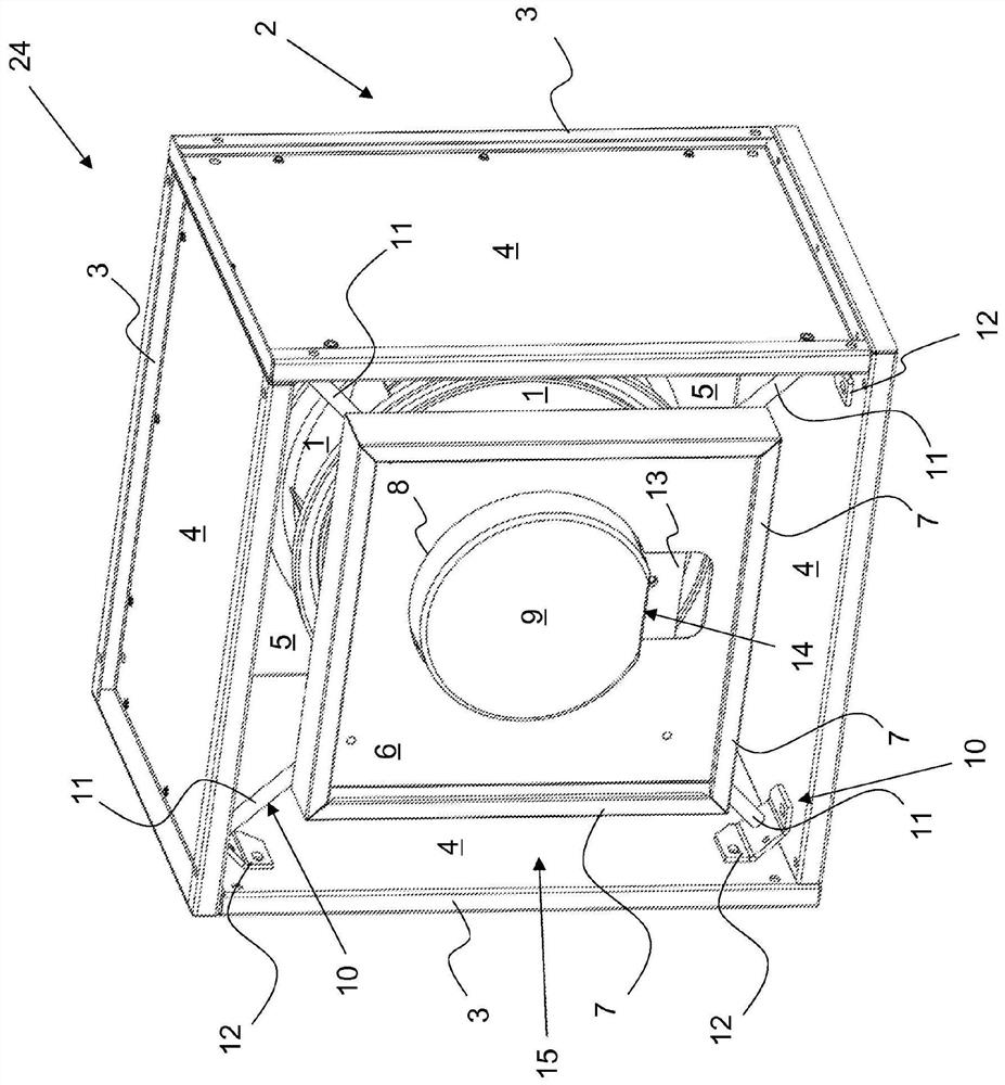
[0044] figure 1 An exemplary embodiment of a fan module 24 according to the invention is shown, in which a radial fan, hereinafter always referred to as fan 1 , is arranged in housing 2 . Fan 1 can be of any fan design.

[0045] A fan module 24 is to be understood as a compact modular component and may be an element of an arrangement having one or more fan modules which may advantageously be arranged directly adjacent and / or one on top of the other, for example A fan module in a fan wall. This also results in a compact design.

[0046] The housing 2 has a frame structure 3 which is closed laterally by side walls 4 . On the inflow side, the housing 2 is closed by a nozzle plate 5 . In the nozzle plate 5 the inlet nozzles 23 for the fan 1 are attached or integrated. The fan module 24 can be fastened via various elements of the housing 2 , in particular via the nozzle plate 5 , the frame structure 3 or the side walls 4 in the flow duct, the ventilation system or another fan ...


PUM


Abstract

The invention relates to a fan module comprising at least one fan (1), possibly including a nozzle plate (5) and a suspension (10). The fan module has a device on the pressure side for reducing or suppressing backflow and equalizing the outflowing air, wherein the device is designed as a mechanical backflow barrier (6), which is arranged approximately in the center of the flow path and blocks the flow cross-section. part. The invention also relates to a device with one or more fan modules (24) in the flow duct.

Description

technical field [0001] The invention relates to a fan module and to the arrangement of one or more such fan modules in a flow duct or similar ventilation system, wherein, in the fan module, on the pressure side, provision is made for reducing or suppressing a backflow of outgoing air installation. Background technique [0002] The term "fan" should be understood in the broadest sense. Typically, the term is used herein to refer to radial fans, diagonal fans or axial fans. In the case of modular use, such fans are arranged in the housing or are connected on the pressure side to flow ducts which generally carry the air flow in the axial direction. The cross-section of the corresponding flow duct is generally rectangular, in particular square or round. [0003] In practice, the flow duct usually has a relatively small cross-section compared to the fan diameter, or the sidewall of the flow duct that deflects the air flowing axially from the fan is arranged relatively close to...

Claims


Application Information

Patent Timeline
Patent Type & Authority Patents(China)
IPC IPC(8): F04D25/08F04D29/42F04D29/58F04D29/70F04D29/44F04D29/62F04D17/16F04D29/66
CPCF04D17/165F04D25/08F04D29/4253F04D29/441F04D29/5826F04D29/626F04D29/664F04D29/667F04D29/703F05D2230/51F05D2230/54F04D17/08F04D25/06F04D29/44F24F7/065F24F11/0001F24F2013/242
Inventor F·勒歇尔M·格勒A·穆勒
Owner ZIEHL ABEGG AG