Novel treadmill motor

A treadmill, a new type of technology, applied in the direction of electromechanical devices, control mechanical energy, sports accessories, etc., can solve the problems of increasing energy consumption, occupying a large space, and consuming motor energy, so as to improve work reliability, save installation space, The effect of eliminating assembly errors

Pending Publication Date: 2019-08-09
SHENZHEN YATENG MOTOR
View PDF0 Cites 1 Cited by
  • Summary
  • Abstract
  • Description
  • Claims
  • Application Information

AI Technical Summary

Problems solved by technology

However, in this type of treadmill, the motor and the roller are independently arranged, and the transmission belt needs to be provided, which leads to a large installation space, which increases the floor space of the treadmill in disguise, and is transmitted through the transmission belt. It consumes the energy of the motor and increases the energy consumption, and errors are prone to occur during the assembly process of the motor, rollers and transmission belts, which will not only further increase energy consumption, but also easily cause the treadmill t

Method used


Image

  • Novel treadmill motor
  • Novel treadmill motor
  • Novel treadmill motor

Examples


Embodiment 1

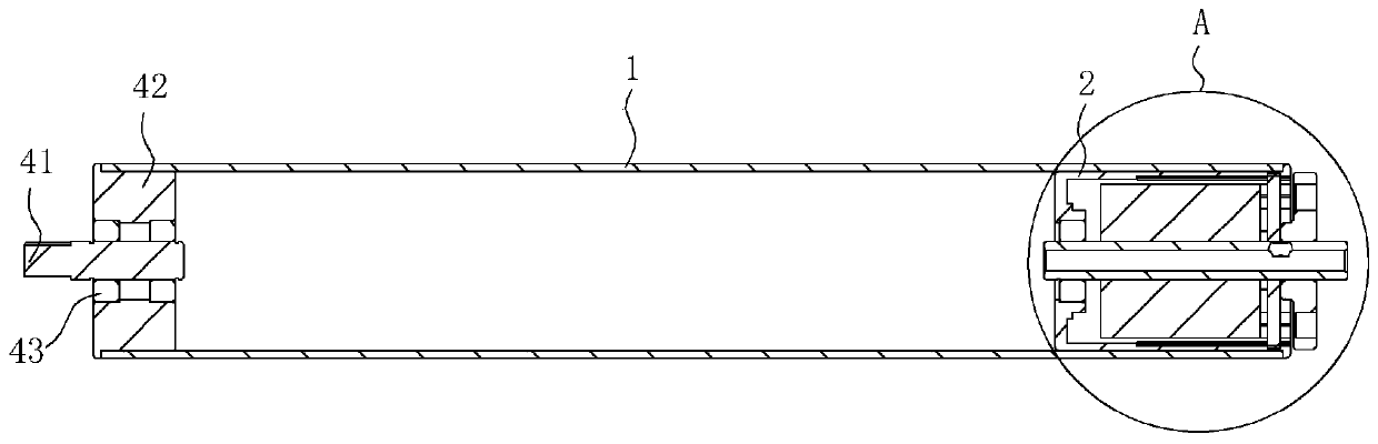
[0018] refer to figure 1 and figure 2 , a new type of treadmill motor in this embodiment includes a treadmill drum 1, a first outer rotor motor 2, an auxiliary shaft 41, a sealing block 42 and an auxiliary bearing 43.

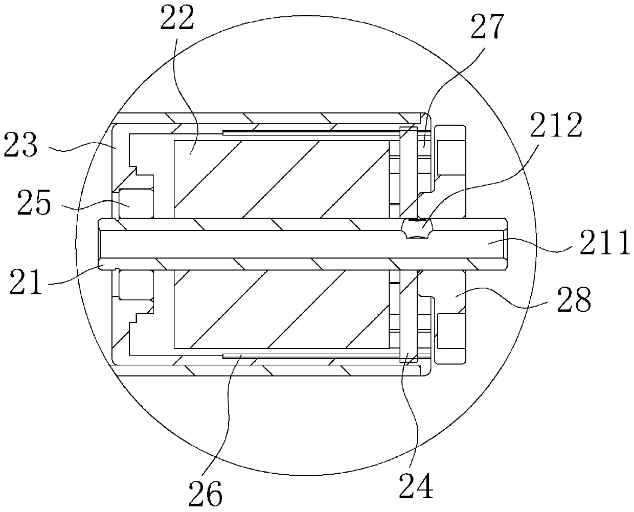
[0019] The first outer rotor motor 2 includes a first shaft 21, a first stator 22, a first outer rotor 23, a first drive plate 24, a first bearing 25, a first permanent magnet 26, a first sealing block 27 and a first cover plate 28. The first stator 22 and the first bearing 25 are respectively fixedly fitted on the first shaft 21, the first drive plate 24 is fixedly fitted on the first shaft 21, and the first outer rotor 23 is fitted on the first bearing 25, so that the first An outer rotor 23 can rotate on the first bearing 25, the first permanent magnet 26 is fixedly embedded in the first outer rotor 23, and the first permanent magnet 26 is opposite to the first stator 22, and the first stator 22 and The first driving board 24 is electrically connected by...

Embodiment 2

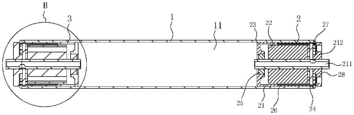
[0025] refer to image 3 and Figure 4 , a new type of treadmill motor in this embodiment includes a treadmill drum 1, a first outer rotor motor 2 and a second outer rotor motor 3.

[0026]The first outer rotor motor 2 includes a first shaft 21, a first stator 22, a first outer rotor 23, a first drive plate 24, a first bearing 25, a first permanent magnet 26, a first sealing block 27 and a first cover plate 28. The first stator 22 and the first bearing 25 are respectively fixedly fitted on the first shaft 21, the first drive plate 24 is fixedly fitted on the first shaft 21, and the first outer rotor 23 is fitted on the first bearing 25, so that the first An outer rotor 23 can rotate on the first bearing 25, the first permanent magnet 26 is fixedly embedded in the first outer rotor 23, and the first permanent magnet 26 is opposite to the first stator 22, and the first stator 22 and The first driving board 24 is electrically connected by wires, and the first driving board 24 ...


PUM


Abstract

The invention discloses a novel treadmill motor which comprises a treadmill roller and a first outer rotor motor. The first outer rotor motor comprises a first shaft, a first stator, a first outer rotor, a first driving plate, a first bearing, a first permanent magnet and a first sealing block. The first stator and the first bearing sleeve the first shaft. The first driving plate is fixedly installed on the first shaft. The first outer rotor sleeves the first bearing. The first permanent magnet is installed in the first outer rotor and is opposite to the first stator. The first driving plate is electrically connected with the first stator. One end of the treadmill roller sleeves the first outer rotor. The first sealing block sleeves the first shaft and is connected with the first driving plate. In the novel treadmill motor, the treadmill roller and the first outer rotor motor are integrated, a large installation space is saved, the energy consumed in transmission process is reduced, the assembly errors in the multi-structure installation are eliminated, and the work reliability of a treadmill is improved.

Description

technical field [0001] The invention relates to the field of treadmill design, in particular to a novel treadmill motor. Background technique [0002] Treadmills are common fitness equipment for families and gyms. Most of the common treadmills now use motors to drive the rollers to rotate through transmission belts, and the rotation of the rollers makes the running belt circulate for users to run. However, in this type of treadmill, the motor and the roller are independently arranged, and the transmission belt needs to be provided, which leads to a large installation space, which increases the floor space of the treadmill in disguise, and is transmitted through the transmission belt. Consuming the energy of the motor increases the energy consumption, and errors are prone to occur in the assembly process of the motor, rollers and transmission belts, which will not only further increase the energy consumption, but also easily cause the treadmill to work unstable. [0003] The...

Claims


Application Information

Patent Timeline
IPC IPC(8): A63B22/02H02K7/10
CPCA63B22/0235A63B22/025H02K7/1016
Inventor 丁剑
Owner SHENZHEN YATENG MOTOR
Why Eureka
Try Eureka