Precision-polishing gripper steering device for sand core die production

A technology for steering equipment and sand core molds, which is applied in the direction of grinding/polishing equipment, casting molding equipment, metal processing equipment, etc., which can solve the problems of immobility and inconvenience for workers, and achieve the effect of easy access and replacement

Active Publication Date: 2019-08-09
ANHUI QUANCHAI TIANHE MACHINERY
View PDF8 Cites 2 Cited by
  • Summary
  • Abstract
  • Description
  • Claims
  • Application Information

AI Technical Summary

Problems solved by technology

[0002] Casting mold means that in order to obtain the structural shape of the part, other easy-to-form materials are used to make the structural shape of the part in advance, and then the mold is placed in the sand mold, so a cavity with the same structural size as the part is formed in the sand mold. Then pour a fluid liquid into the cavity, and after the liquid cools and solidifies, it can form a part with exactly the same shape and structure as the mold; sand casting is a kind of casting process, and the casting mold used in sand casting is generally composed of an outer sand mold and a mold. The core is combined, and in the production process of the sand core mold, the sand core mold will be polished and polished. However, the direction and position of the existing sand core mold production are generally fixed. When grinding and polishing the different sides of the sand core mold, it is necessary to stop the grinding and polishing equipment, and then manually adjust the sand core mold, which brings inconvenience to the workers. Therefore, we propose a sand core mold for production. Fine throwing gripper steering equipment is used to solve the above problems

Method used


Image

  • Precision-polishing gripper steering device for sand core die production
  • Precision-polishing gripper steering device for sand core die production
  • Precision-polishing gripper steering device for sand core die production

Examples


Embodiment Construction

[0020] The following will clearly and completely describe the technical solutions in the embodiments of the present invention with reference to the accompanying drawings in the embodiments of the present invention. Obviously, the described embodiments are only some, not all, embodiments of the present invention. Based on the embodiments of the present invention, all other embodiments obtained by persons of ordinary skill in the art without making creative efforts belong to the protection scope of the present invention.

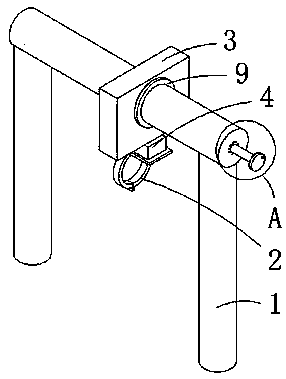
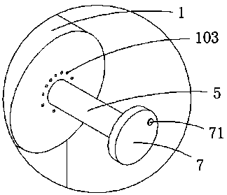
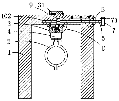
[0021] see Figure 1-7 , the present invention provides a technical solution: a fine throwing gripper steering device for sand core mold production, including a U-shaped support rod 1, a gripper 2 and a rotating plate 3, the rotating plate 3 is provided with a circular through hole 301, And the rotating plate 3 is sleeved on the ejector rod of the U-shaped support rod 1 through the circular through hole 301, and the ejector rod of the U-shaped supporting rod 1...


PUM


Abstract

The invention discloses a precision-polishing gripper steering device for sand core die production. The precision-polishing gripper steering device for sand core die production comprises a U-shaped support rod, a gripper and a rotating plate, wherein a circular through hole is formed in the rotating plate; the rotating plate sleeves a top rod of the U-shaped support rod through the circular through hole; an annular plate for limiting the rotating plate from moving is fixedly connected onto the top rod of the U-shaped support rod; a connecting block is rotatably connected to the lower surface of the rotating plate; the upper end surface of the gripper is fixedly connected to the lower surface of the connecting block; a holding groove is formed in the lower surface of the top rod of the U-shaped support rod; a rotating rod is rotatably connected onto the side wall of the holding groove; and a groove for the rotating rod to move left and right is formed in the side wall of the holding groove. According to the precision-polishing gripper steering device for sand core die production provided by the invention, the direction of a precision-polishing gripper can be effectively adjusted, objects on the gripper can be conveniently ground and polished, the position of the precision-polishing gripper can be adjusted, the objects on the precision-polishing gripper can be conveniently pickedand replaced, and convenience is brought for working personnel.

Description

technical field [0001] The invention relates to the technical field of sand core mold production equipment, in particular to a precision throwing gripper steering equipment for sand core mold production. Background technique [0002] Casting mold means that in order to obtain the structural shape of the part, other easy-to-form materials are used to make the structural shape of the part in advance, and then the mold is placed in the sand mold, so a cavity with the same structural size as the part is formed in the sand mold. Then pour a fluid liquid into the cavity, and after the liquid cools and solidifies, it can form a part with exactly the same shape and structure as the mold; sand casting is a kind of casting process, and the casting mold used in sand casting is generally composed of an outer sand mold and a mold. The core is combined, and in the production process of the sand core mold, the sand core mold will be polished and polished. However, the direction and positio...

Claims


Application Information

Patent Timeline
Patent Type & Authority Applications(China)
IPC IPC(8): B22C9/10B22C9/12B22C9/18B24B19/20B24B41/06
CPCB22C9/10B22C9/12B22C9/18B24B19/20B24B41/06
Inventor 张印
Owner ANHUI QUANCHAI TIANHE MACHINERY
Why Eureka
Try Eureka