Straight tube pin hook type spherical omnidirectional wheel

A universal wheel and pin-hook type technology, applied in the field of universal wheels, can solve the problems of damage to the locking mechanism, failure to achieve the effect, too flexible movement, etc., and achieve the effect of simple production, easy realization, and convenient use

Pending Publication Date: 2019-08-09
武成阁
View PDF9 Cites 1 Cited by
  • Summary
  • Abstract
  • Description
  • Claims
  • Application Information

AI Technical Summary

Problems solved by technology

However, its movement is too flexible, causing movement when it is not needed
In order to solve this problem, in the prior art, a locking mechanism is provided on the wheel to lock the wheel so that it does not move, but in fact, because the wheel is easy to move, this locking mechanism cannot realize t

Method used


Image

  • Straight tube pin hook type spherical omnidirectional wheel

Examples


Embodiment 1

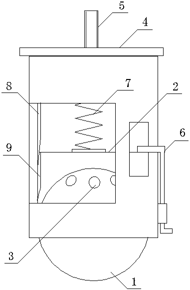
[0015] Such as figure 1 As shown, a straight pin-hook type spherical universal wheel includes a rolling ball 1, an inner cylinder 2 covering the rolling ball 1, and several guide guides in contact with the surface of the rolling ball are arranged above the inside of the inner cylinder 2. Ball 3, an outer cylinder 4, the top of the outer cylinder 4 is equipped with fixing bolts 5 for connecting with other devices, a pin hook assembly 6 is arranged on the outer circumference of the outer cylinder 4, the pin hook assembly 6 includes a fixed frame, and is installed on a fixed On the frame, the pin hook pivoted by the fixed frame is provided with a pin hook groove on the outer cylinder body, and the hook of the pin hook penetrates into the pin hook groove to press on the top surface of the inner cylinder body, and the inner height of the outer cylinder body is greater than that of the inner cylinder body. The combined height of cylinder and rolling ball.

[0016] The pin hook asse...

Embodiment 2

[0018] As a structural design of Example 1, a compression spring 7 is arranged inside the outer cylinder 4 , one end of the compression spring 7 bears against the top surface of the inner cylinder 2 , and the other end bears against the inner surface of the top of the outer cylinder 4 .

[0019] The inner cylinder 2 and the outer cylinder 4 are cylinders, a spring sleeve is arranged at the center of the top surface of the inner cylinder 2, a spring sleeve is arranged at the center of the inner top surface of the outer cylinder 4, and the two ends of the compression spring 7 are respectively located Inside the two spring sleeves.

[0020] This embodiment is an optimized design of Example 1. A compression spring 7 is arranged between the inner cylinder body 2 and the inner cavity of the outer cylinder body 4, and the shock absorption is realized through the compression spring 7, so as to protect the structure of the present invention and enable the The rolling ball is firmly in ...

Embodiment 3

[0022] As a further structural design of Example 2, two pin hook assemblies 6 are provided, and the outer cylinder 4 is arranged symmetrically.

[0023] A guide protrusion 8 is arranged inside the outer cylinder 4 , and a guide groove 9 is arranged on the upper outer surface of the inner cylinder, and the guide protrusion 8 is located in the guide groove 9 .

[0024] The design of this implementation example takes into account the ease of use of the pin hook assembly and the cooperation between the outer cylinder and the inner cylinder. During operation, the mutual rotation between the outer surface of the inner cylinder and the inner surface of the outer cylinder is reduced. friction.


PUM


Abstract

The invention discloses a straight tube pin hook type spherical omnidirectional wheel which comprises a rolling sphere, an inner tube body covering the rolling sphere, a plurality of movement-guidingrolling balls and an outer tube body, wherein the movement-guiding rolling balls are arranged at the inner upper part of the inner tube body and in contact with the surface of the rolling sphere; a fixing bolt is mounted on the top of the outer tube body and used for connecting to other devices; pin hook assemblies are arranged on the outer circumference of the outer tube body; the pin hook assemblies comprise fixing frames and pin hooks; the pin hooks are mounted on the fixing frames and pivoted on the fixing frames; a pin hook groove is arranged in the outer tube body; hooks of the pin hooksare utilized to penetrate into the pin hook groove and to be pressed against the top surface of the inner tube body; and the tube body inner height of the outer tube body is greater than the height of the inner tube body and the rolling sphere after combination. In the straight tube pin hook type spherical omnidirectional wheel, the rolling sphere, the rolling balls and the inner tube body are used as the omnidirectional wheel; the outer tube body is used as a lifting support leg and supported by a compression spring; and a guide protrusion cooperates with a guide groove. By virtue of the pinhook assemblies, the straight tube pin hook type spherical omnidirectional wheel can not only preserve all functions of the omnidirectional wheel but also realize the same function of an ordinary table leg when movement is not required. The structure is simple to manufacture, easy to implement and convenient to use.

Description

technical field [0001] The invention relates to a universal wheel, in particular to a straight pin hook type spherical universal wheel. Background technique [0002] The swivel caster is a movable caster. Its structure allows 360-degree rotation horizontally. It is often used on tables, chairs, counters, equipment and other institutions that require movement. The structure of universal wheel has the combination of fixed frame, movable frame and wheel, and wheel has roller and ball etc. The purpose of these structures is to make the universal wheel freely realize 360 ​​degree rotation. However, its movement is too flexible, causing it to move when it is not needed. In order to solve this problem, in the prior art, a locking mechanism is provided on the wheel to lock the wheel so that it does not move, but in fact, because the wheel is easy to move, this locking mechanism cannot realize the desired Effect. For example, after a counter, table or equipment is placed in place...

Claims


Application Information

Patent Timeline
IPC IPC(8): B60B33/00B60B33/02B60B33/08
CPCB60B33/02B60B33/08B60B33/0078
Inventor 武成阁
Owner 武成阁
Why Eureka
Try Eureka