Methods, computer programs, devices, and encoders for signal error correction

A computer program, signal error technology, applied in recording signal processing, using multiple codes for error correction/detection, instrumentation, etc., can solve problems such as low efficiency, imperfect measurement, signal disturbance, etc.

Active Publication Date: 2019-08-09
LEINE & LINDE
View PDF12 Cites 8 Cited by
  • Summary
  • Abstract
  • Description
  • Claims
  • Application Information

AI Technical Summary

Problems solved by technology

However, the signal measured by the encoder may be disturbed by machine parts that are not perfectly aligned, e.g. due to fatigue or an external magnetic field disturbing the encoder's measurement sensor
For example, when generating incremental control signals, such perturbations can lead to imperfect measurements which, if not properly compensated, will lead to downstream inefficiencies when used

Method used


Image

  • Methods, computer programs, devices, and encoders for signal error correction
  • Methods, computer programs, devices, and encoders for signal error correction
  • Methods, computer programs, devices, and encoders for signal error correction

Examples


Embodiment Construction

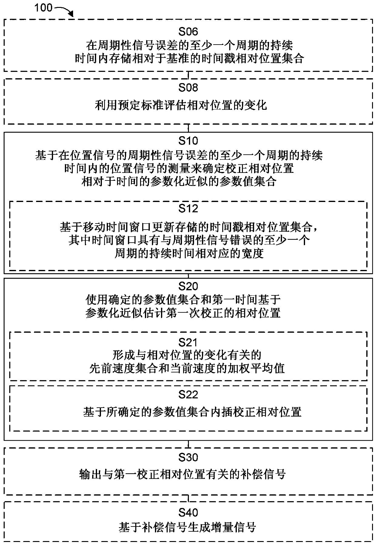
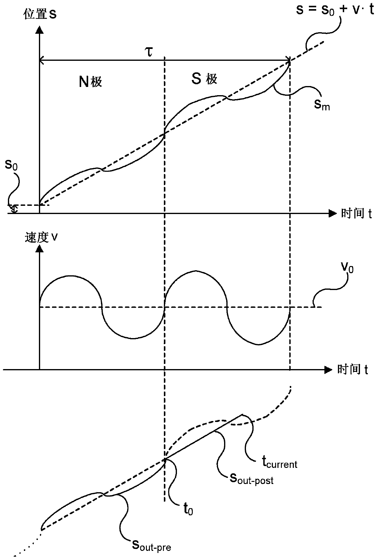
[0029] The disclosed method takes advantage of the fact that in many real-world scenarios, the generated motion has a well-known behavior, and it is expected that the signal measuring the position relative to the reference will exhibit certain characteristics that depend on the position-related motion. For example, in the case of a constant speed motion, the expected speed-time relationship shows a constant behavior, that is, the speed will be constant with respect to time. Likewise, the expected position will change linearly. In some cases, deviations from these expected behaviors can be considered errors. In particular, periodic deviations from expected behavior can often be interpreted as errors, and by determining these errors, the effects of these errors can be resolved.

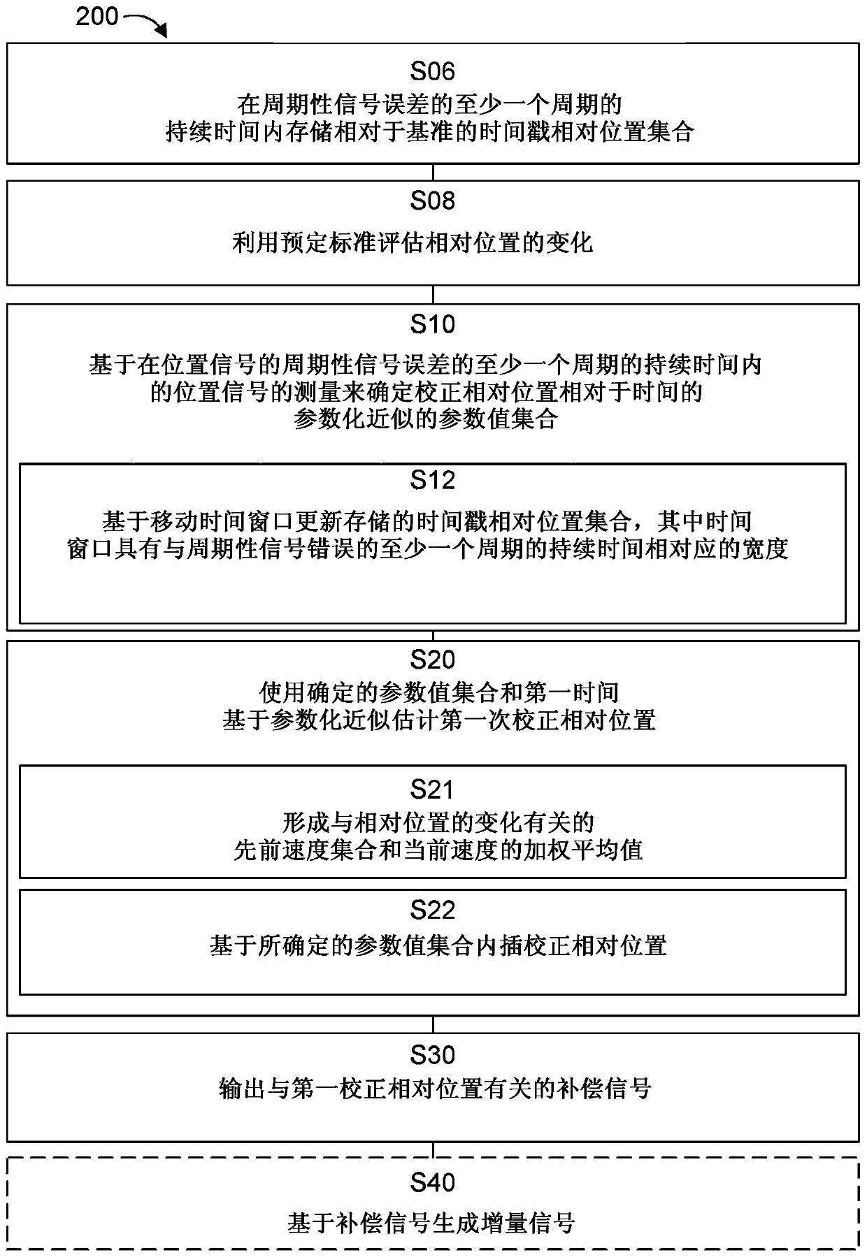
[0030] Figure 1a The method steps of a method 100 for signal error correction of a position signal related to the relative position of at least one sensor with respect to a reference are shown. Figure 1b...


PUM


Abstract

The invention relates to methods, computer programs, devices, and encoders for signal error correction. A method (100) for signal error correction of a position signal relating to a relative positionof at least one sensor with respect to a reference, includes determining (S10) a set of parameter values of a parameterized approximation of a corrected relative position with respect to time based onmeasurements of the position signal over a duration of at least one period of a periodic signal error of the position signal. The method further includes estimating (S20) a first corrected relative position at a first time based on the parameterized approximation using the determined set of parameter values and the first time.

Description

Technical field [0001] The present disclosure relates to signal error correction. In particular, the present disclosure relates to a method for signal error correction of a position signal related to the relative position of at least one sensor with respect to a reference. The method also involves corresponding computer programs, equipment and encoders. Background technique [0002] Many machine operations rely on registering information related to the current machine status and using the registered information to correct the machine's operation or control downstream functions. Encoders are usually used to record relevant information and convert the information into suitable signals, such as incremental control signals. However, for example, due to fatigue or external magnetic fields disturbing the measurement sensor of the encoder, the signal measured by the encoder may be disturbed by machine parts that are not perfectly aligned. For example, when generating incremental cont...

Claims


Application Information

Patent Timeline
Patent Type & Authority Applications(China)
IPC IPC(8): G01D18/00
CPCG01D18/00G01D5/24495G01D5/2451G01D5/24471G01D5/24476G01D5/2454G01P3/489G11B20/1833H03M13/31
Inventor 弗雷德里克·古斯塔夫松
Owner LEINE & LINDE
Why Eureka
Try Eureka