Eureka AIR delivers breakthrough ideas for toughest innovation challenges, trusted by R&D personnel around the world.

A Fast Super-resolution Imaging Method for Scanning Radar

A technology of super-resolution imaging and scanning radar, which is applied in the direction of instruments, measuring devices, and utilization of re-radiation, can solve the problems of reducing the dimensionality of data processing and high dimensionality of operations, so as to improve computing efficiency, improve imaging processing efficiency, and maintain super Resolving Effects on Imaging Performance

Active Publication Date: 2021-01-26
UNIV OF ELECTRONICS SCI & TECH OF CHINA
View PDF11 Cites 0 Cited by
  • Summary
  • Abstract
  • Description
  • Claims
  • Application Information

AI Technical Summary

Problems solved by technology

[0005] The purpose of the present invention is to solve the problem of high operational dimension in the existing super-resolution technology, and proposes a fast super-resolution imaging method for scanning radar, which uses a low-rank random matrix to realize the compression of the dimension of the antenna pattern measurement matrix; through QR Decomposition, to obtain the orthogonal basis vector of the compressed measurement matrix, realize the information extraction of the antenna measurement matrix, reduce the dimensionality of data processing while maintaining performance

Method used


Image

  • A Fast Super-resolution Imaging Method for Scanning Radar
  • A Fast Super-resolution Imaging Method for Scanning Radar
  • A Fast Super-resolution Imaging Method for Scanning Radar

Examples


Embodiment Construction

[0057] Embodiments of the present invention will be further described below in conjunction with the accompanying drawings.

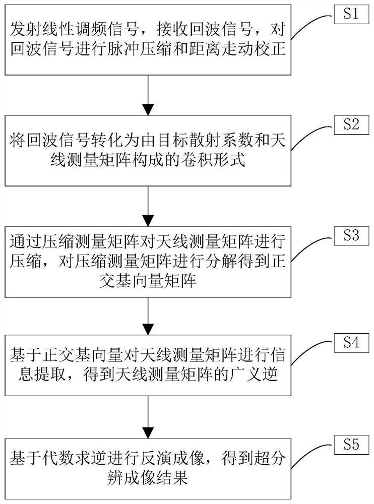
[0058] see figure 1 , the present invention proposes a scanning radar fast super-resolution imaging method, which is realized by the following steps:

[0059] S1. Transmitting a chirp signal, receiving an echo signal, performing pulse compression and distance walking correction on the echo signal, and obtaining an echo signal after pulse compression and distance walking correction.

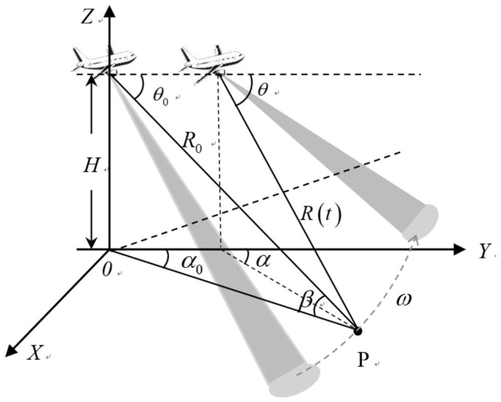
[0060] In this embodiment, the airborne scanning radar motion model is as follows figure 2 The specific system parameters of the airborne platform are shown in Table 1.

[0061] Simulation parameters value carrier frequency 10GHz time width 2μs bandwidth 75Mhz Movement speed 75m / s pulse repetition frequency 1000Hz scanning speed 10° / s scan range ±10°

[0062] Table 1 Radar system parameter table

[0063] Accor...


PUM


Abstract

The invention provides a scanning radar fast super-resolution imaging method, which belongs to the field of radar imaging. The invention is used to improve the imaging processing efficiency of the existing scanning radar super-resolution imaging method. Firstly, based on the scanning radar azimuth echo convolution model, a low-rank random matrix is ​​used to compress the dimension of the antenna pattern measurement matrix; secondly, the compressed The measurement matrix is ​​orthogonalized to obtain the orthogonal basis vectors, and the generalized inverse of the antenna measurement matrix is ​​obtained. Finally, the generalized inverse is used to quickly solve the convolution inversion problem to realize super-resolution imaging of scanning radar forward-looking targets. Compared with the traditional super-resolution imaging method, the method of the invention can improve the calculation efficiency of imaging processing while maintaining the performance of super-resolution imaging.

Description

technical field [0001] The invention belongs to the field of radar imaging, in particular to a scanning radar fast super-resolution imaging method. Background technique [0002] The imaging of the forward-looking area of ​​the airborne scanning radar is widely used in fields such as battlefield reconnaissance, sea imaging, autonomous landing of aircraft, and material airdrops. Since conventional single-station SAR and DBS technologies cannot realize forward-looking imaging, real-beam scanning radar beam sharpening technology has become an important technical means to achieve forward-looking imaging. [0003] In the prior art, regularization is used to improve the ill-conditionedness of the matrix by adding a regularization term. When the added regularization term is L 2 Norm, it is the classic Tikhonov regularization method. However, when the Tikhonov regularization method is applied, it will face a matrix inversion operation, and its operational complexity is O(n 3 ), th...

Claims


Application Information

Patent Timeline
Patent Type & Authority Patents(China)
IPC IPC(8): G01S13/89
CPCG01S13/89
Inventor 张寅庹兴宇毛德庆张文涛张永超裴季方黄钰林郭德明杨建宇
Owner UNIV OF ELECTRONICS SCI & TECH OF CHINA
Why Eureka
Eureka Blog
Learn More