
Compressor bleed air module flow path design method

A design method and compressor technology, applied in computer-aided design, design optimization/simulation, calculation, etc., can solve the problem that it is difficult to meet the design requirements of high-performance compressors, the forward design of the flow path of the air-bleed module, and the impact on industrial development cycle and other issues to achieve the effect of shortening the development cycle, reducing scientific research costs, and controlling potential risks

Pending Publication Date: 2019-08-09
AECC SHENYANG ENGINE RES INST
View PDF4 Cites 0 Cited by
  • Summary
  • Abstract
  • Description
  • Claims
  • Application Information

AI Technical Summary

Problems solved by technology

The disadvantage of this method is that the newly designed air-bleed module of the compressor is required to be similar in size, structure, and volume of air-bleed to the original air-bleed module. Due to its limitations, it brings corresponding technical risks, and problems are often discovered only in the experimental stage, which affects the industrial development cycle and leads to increased development costs
In addition, the traditional method is difficult to carry out the forward design of the flow path of the new form of bleed air module, and it is difficult to meet the design needs of high-performance compressors

Method used


Image

  • Compressor bleed air module flow path design method
  • Compressor bleed air module flow path design method
  • Compressor bleed air module flow path design method

Examples


Embodiment Construction

[0033] In order to make the purpose, technical solution and advantages of the application more clear, the technical solution in the embodiment of the application will be described in more detail below in conjunction with the drawings in the embodiment of the application. In the drawings, the same or similar reference numerals denote the same or similar elements or elements having the same or similar functions throughout. The described embodiments are some, but not all, embodiments of the application. The embodiments described below by referring to the figures are exemplary, and are intended to explain the present application, and should not be construed as limiting the present application. Based on the embodiments in this application, all other embodiments obtained by persons of ordinary skill in the art without creative efforts fall within the protection scope of this application. Embodiments of the present application will be described in detail below in conjunction with th...


PUM


Abstract

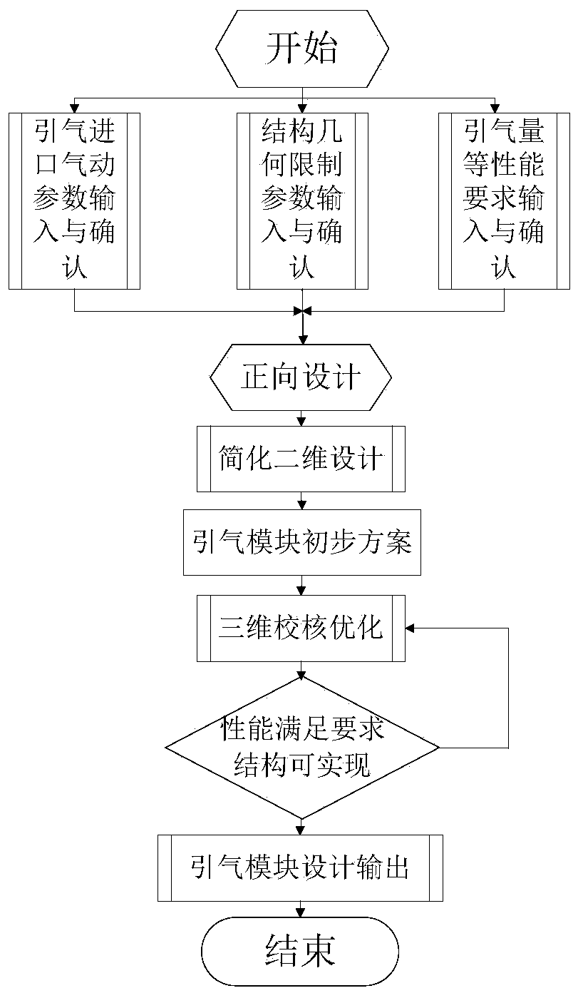
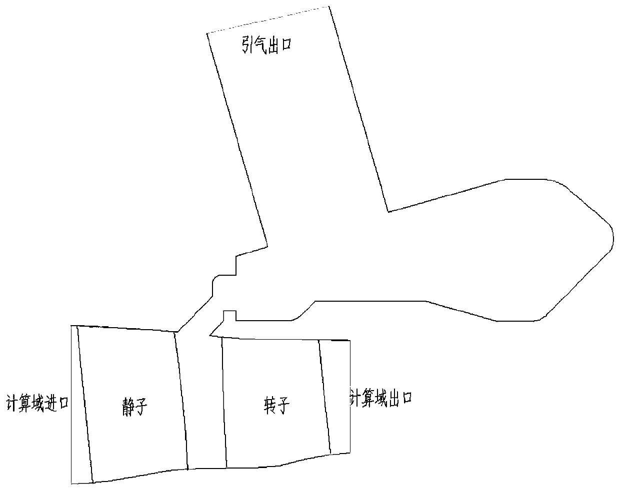
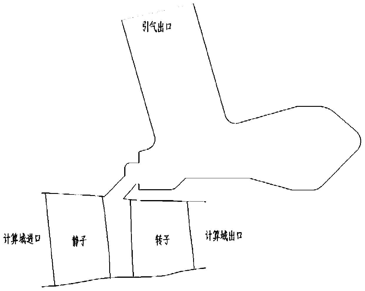
The invention belongs to the field of aero-engine design, and particularly relates to a compressor bleed air module flow path design method. The method comprises the steps that 1, obtaining compressorair entraining module parameters, wherein the parameters comprise the structural geometric limiting size parameter, the air entraining inlet pneumatic parameter and the air entraining module functionparameter; step 2, establishing a two-dimensional flow path model according to the compressor air entraining module parameters, and optimizing the two-dimensional flow path model; step 3, establishing a three-dimensional flow path model according to the two-dimensional flow path model, and optimizing the three-dimensional flow path model; and 4, outputting a compressor bleed air module flow pathdesign result. The simplified two-dimensional flow path model is established according to extraction of the compressor air entraining module parameters, the bleed air module flow path design method isexpanded from two dimensions to three dimensions, forward design of compressor bleed air is achieved, the potential risk of novel bleed air module design is effectively controlled, reduction of the scientific research cost is facilitated, and the development period of compressor products is shortened.

Description

technical field [0001] The application belongs to the field of aero-engine design, and in particular relates to a flow path design method of a compressor bleed air module. Background technique [0002] The task of flow path design of the compressor bleed air module is to obtain an effective flow path of the compressor bleed air module for the given design indicators such as the position of the compressor bleed air structure and the amount of compressor bleed air under the constraints of the structural size. The quality of the flow path design of the bleed air module of the compressor directly affects the bleed air volume and pressure loss of the compressor, and even affects the performance of the compressor. The flow path design and evaluation of the bleed air module of the compressor are indispensable in the forward design process of the compressor link. [0003] The design process of the bleed air module is closely related to engineering, and the aerodynamics and structur...

Claims


Application Information

Patent Timeline
Patent Type & Authority Applications(China)
IPC IPC(8): G06F17/50
CPCG06F30/15G06F30/20
Inventor 赵月振郭海宁尹松刘太秋李惠莲
Owner AECC SHENYANG ENGINE RES INST
Learn More