Thin-walled workpiece omnidirectional vibration measurement method and system based on binocular vision optical flow tracking

A technology of vibration measurement and optical flow tracking, which is applied in image data processing, instruments, calculations, etc., can solve problems such as increasing structural quality, low spatial resolution, and weak strength, and achieves reduced noise impact, high measurement accuracy, and practicality high effect

Pending Publication Date: 2019-08-09
HUNAN UNIV OF SCI & TECH
View PDF4 Cites 2 Cited by
  • Summary
  • Abstract
  • Description
  • Claims
  • Application Information

AI Technical Summary

Problems solved by technology

At the same time, thin-walled parts also have the characteristics of relatively low rigidity, weak strength and large size, which are likely to cause problems such as noise and instability. During the operation of the equipment, it may even cause serious mechanical failures, resulting in major safety accidents. Efficient and accurate Vibration measurement of thin-walled parts for real-time monitoring
Conventional vibration measurement methods often use contact measurement such as accelerometer sensors, gyroscope sensors, and piezoelectric ceramic sensors. These methods all use sensors, which increase the quality of the structure and produce load effects that change the original dynamic performance of thin-walled parts. There are also problems such as low spatial resolution and difficult sensor installation.

Method used


Image

  • Thin-walled workpiece omnidirectional vibration measurement method and system based on binocular vision optical flow tracking
  • Thin-walled workpiece omnidirectional vibration measurement method and system based on binocular vision optical flow tracking
  • Thin-walled workpiece omnidirectional vibration measurement method and system based on binocular vision optical flow tracking

Examples


Embodiment Construction

[0057] The following will clearly and completely describe the technical solutions in the embodiments of the present invention with reference to the accompanying drawings in the embodiments of the present invention. Obviously, the described embodiments are only some, not all, embodiments of the present invention. Based on the embodiments of the present invention, all other embodiments obtained by persons of ordinary skill in the art without making creative efforts belong to the protection scope of the present invention.

[0058] In order to make the above objects, features and advantages of the present invention more comprehensible, the present invention will be further described in detail below in conjunction with the accompanying drawings and specific embodiments.

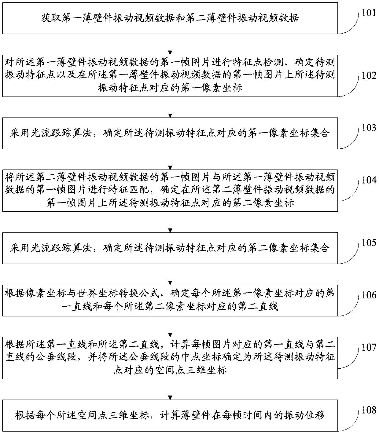
[0059] Such as figure 1 As shown, this embodiment provides a method for measuring omnidirectional vibration of thin-walled parts based on binocular visual optical flow tracking, including:

[0060] Step 101: Obta...


PUM


Abstract

The invention discloses a thin-walled workpiece omnidirectional vibration measurement method and system based on binocular vision optical flow tracking, and relates to the technical field of thin-walled workpiece vibration measurement, and the method comprises the steps: obtaining thin-walled workpiece vibration video data shot by two cameras; performing feature point detection on the first frameof picture shot by the left camera, and selecting to-be-detected vibration feature points; performing feature matching on the first frame of picture of the right camera and the first frame of pictureof the left camera to obtain pixel coordinates corresponding to the vibration feature point to be detected; using an optical flow tracking algorithm to obtain pixel coordinates of to-be-measured vibration feature points on the second frame to the last frame of picture shot by the left camera and the right camera; and according to the pixel coordinates, calculating the nearest distance between thedifferent-plane straight lines, determining the midpoint coordinate of the nearest distance as the spatial three-dimensional coordinate of the to-be-measured vibration characteristic point, and further calculating the vibration displacement of the thin-wall part in each frame of time. The method disclosed by the invention is simple to operate, high in measurement precision and high in practicability, and non-contact vibration measurement without a load effect can be realized.

Description

technical field [0001] The invention relates to the technical field of vibration measurement of thin-walled parts, in particular to a method and system for omnidirectional vibration measurement of thin-walled parts based on binocular visual optical flow tracking. Background technique [0002] Thin-walled parts have been widely used in engineering fields due to their advantages of light weight, compact structure and strong bearing capacity. At the same time, thin-walled parts also have the characteristics of relatively low rigidity, weak strength and large size, which are likely to cause problems such as noise and instability. During the operation of the equipment, it may even cause serious mechanical failures, resulting in major safety accidents. Efficient and accurate Vibration measurement of thin-walled parts for real-time monitoring. Conventional vibration measurement methods often use contact measurement such as accelerometer sensors, gyroscope sensors, and piezoelectri...

Claims


Application Information

Patent Timeline
Patent Type & Authority Applications(China)
IPC IPC(8): G06T7/73G06T7/00
CPCG06T7/73G06T7/97G06T2207/30164
Inventor 伍济钢邵俊赵前程杜义贤阳德强袁继广
Owner HUNAN UNIV OF SCI & TECH
Why Eureka
Try Eureka