
Display panel and driving method thereof

A technology of a display panel and a driving method, which is applied to static indicators, electrical components, instruments, etc., can solve the problems such as the inability to meet the number of backlight partitions and the limitation of the address range of chip selection, and achieves an increase in the number of backlight partitions, a better viewing effect, and a reduction in the number of backlight partitions. afterimage effect

Inactive Publication Date: 2019-08-09
TCL CHINA STAR OPTOELECTRONICS TECH CO LTD
View PDF4 Cites 3 Cited by
  • Summary
  • Abstract
  • Description
  • Claims
  • Application Information

AI Technical Summary

Problems solved by technology

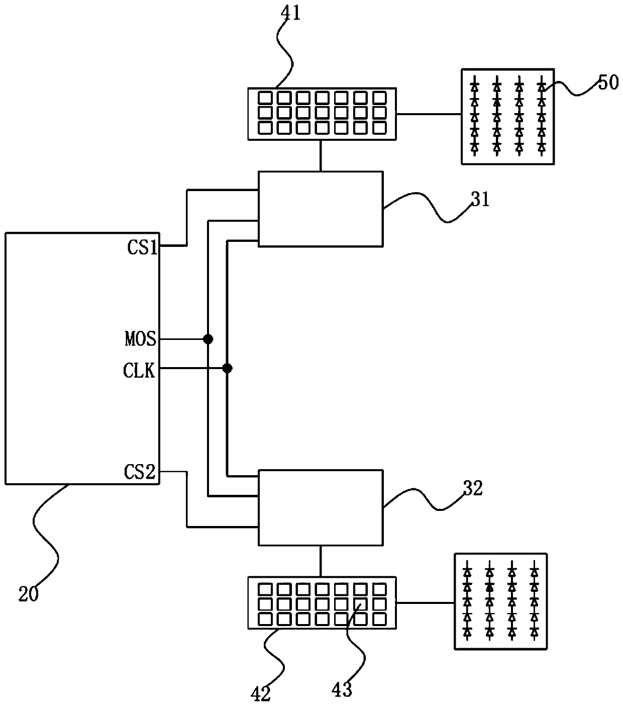
[0004] The present invention provides a display panel to solve the problem that in the existing display panel, limited by the chip selection address range of the control unit, one control module can only be used to drive less than 30 control units, which cannot meet the needs of higher backlight partitions. Product technical issues

Method used


Image

  • Display panel and driving method thereof
  • Display panel and driving method thereof
  • Display panel and driving method thereof

Examples


Embodiment Construction

[0037] The following descriptions of the various embodiments refer to the accompanying drawings to illustrate specific embodiments in which the invention may be practiced. The directional terms mentioned in the present invention, such as [top], [bottom], [front], [back], [left], [right], [inside], [outside], [side], etc., are only for reference The orientation of the attached schema. Therefore, the directional terms used are used to illustrate and understand the present invention, but not to limit the present invention. In the figures, structurally similar elements are denoted by the same reference numerals.

[0038] The present invention aims at the technical problem that in the existing display panel, limited by the chip selection address range of the control unit, one control module can only be used to drive less than 30 control units, which cannot satisfy products with a higher number of backlight partitions. The present invention can solve the above-mentioned problems. ...


PUM


Abstract

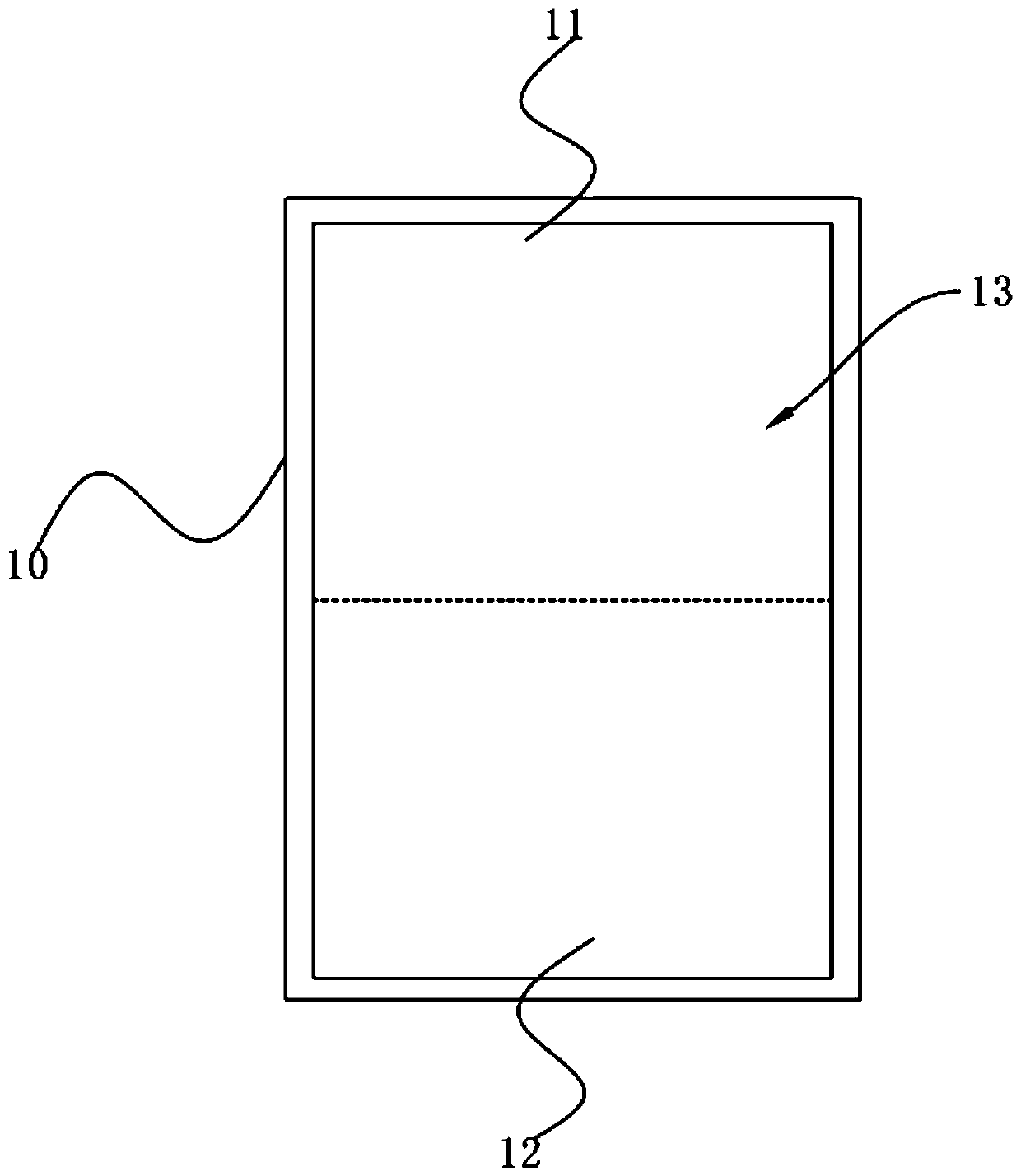
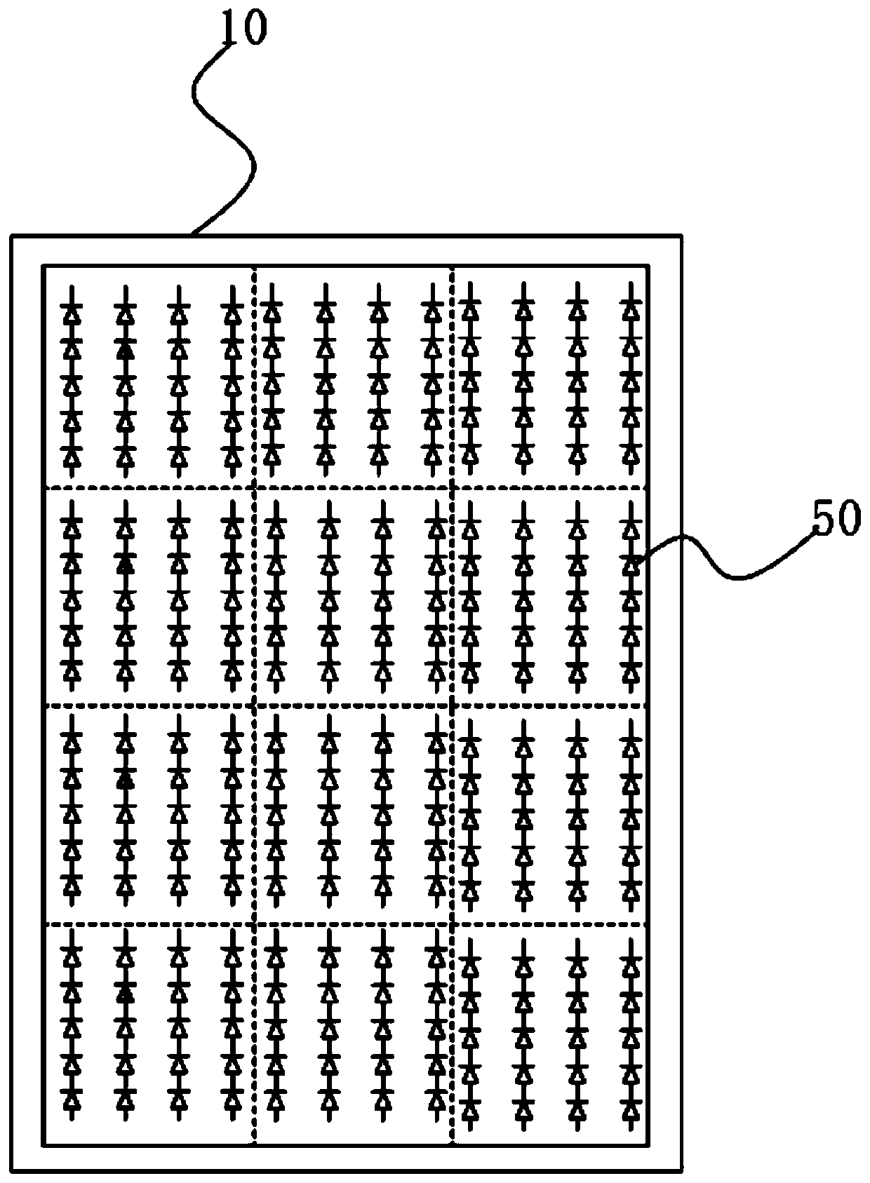
The invention provides a display panel. The display panel comprises a backlight module and a display screen body, the backlight module comprises a central control panel, a control module, a first driving module, a second driving module and a plurality of light emitting diodes. The control module comprises a first control unit and a second control unit which are electrically connected with the central control board, the first driving module is electrically connected with the first control unit, and the second driving module is electrically connected with the second control unit; the display screen body comprises a first split body and a second split body, the light emitting diode corresponding to the first split body is electrically connected with the first driving module, and the light emitting diode corresponding to the second split body is electrically connected with the second driving module. At least two control modules are simultaneously mounted on one central control board, and more driving modules are controlled through more control modules, so that the number of backlight partitions is increased on the premise that the central control board is not increased.

Description

technical field [0001] The present invention relates to the field of display technology, in particular to a display panel and a driving method thereof. Background technique [0002] At present, TCON (Timer Control Board, central control board) controls local backlight adjustment technology (Local Dimming) is widely used in TV backlight drive solutions, the above-mentioned system is mainly composed of TCON, MCU (MicrocontrollerUnit, micro control unit) and LED Driver (liquid crystal drive) IC consists of three parts. TCON performs partition sampling and brightness statistics on the input full-screen image, and sends the backlight driving data to the MCU in real time through the SPI1 (Serial Peripheral Interface) interface, and the MCU then addresses and locates the LED Driver IC where the partition is located through SPI2. By using pulse width modulation (PWM) and opening a specific output channel of the corresponding IC, the backlight in the area and the image screen can be...

Claims


Application Information

Patent Timeline
Patent Type & Authority Applications(China)
IPC IPC(8): G09G3/34
CPCG09G3/342G09G3/3426G09G2310/0221G09G2320/0686G09G2360/04H05B45/30G09G2310/08G09G2320/0257
Inventor 黄生
Owner TCL CHINA STAR OPTOELECTRONICS TECH CO LTD
Learn More