Voltage sag loss assessment method considering protection action time

A technology of voltage sag and protection action, applied to emergency protection circuit devices, electrical components, etc., can solve problems such as failure to consider the action time of protection devices, economic loss hazards of industrial users, and unavailability of sensitive equipment

Active Publication Date: 2019-08-09
南京和源电力实业有限公司
View PDF4 Cites 6 Cited by
  • Summary
  • Abstract
  • Description
  • Claims
  • Application Information

AI Technical Summary

Problems solved by technology

[0002] As various sensitive loads are put into the power grid, power disturbances such as voltage sags (including short-term voltage interruptions) may cause user production interruptions, and sensitive equipment cannot obtain the required quality of power.
The voltage sag may not cause its shutdown, but it will affect or even destroy the continuous work of industrial user equipment or industrial production lines, and the economic losses and harm caused to industrial users are very serious
[0003] The existing loss assessment methods have some defects in the evaluation methods and the consideration of influencing factors.
One is that it does not take into account the action time of the protection device equipped on the line where the sensitive equipment is located, and does not distinguish whether the voltage sag will cause the equipment to shut down; the second is that the duration of the voltage sag is affected by various factors such as seasons and industrial types. The current loss assessment method ignores the analysis and mining of historical voltage sag big data, and does not apply it to the loss assessment, and the assessment method lacks accuracy

Method used


Image

  • Voltage sag loss assessment method considering protection action time
  • Voltage sag loss assessment method considering protection action time
  • Voltage sag loss assessment method considering protection action time

Examples


Embodiment Construction

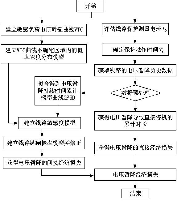
[0062] The present invention is described in further detail now in conjunction with accompanying drawing.

[0063] Such as Figure 1 to Figure 3 As shown, the present invention provides a method for evaluating voltage sag loss considering protection action time, comprising the following steps:

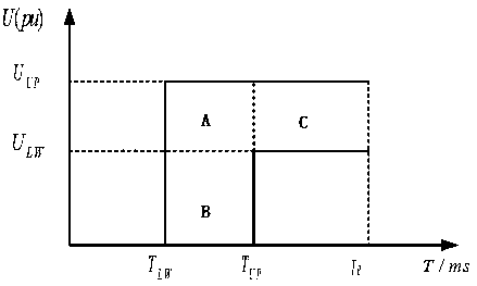
[0064] S1. Evaluate the protection measurement current I of the equipment on the target line 0 . I 0 It is the basis for the protection device to judge the fault, and its purpose is to protect the electrical equipment, especially the precision voltage-sensitive equipment such as over-current and quick-break protection. The setting of the short-circuit short-time delay current needs to be set according to the minimum short-circuit current at the end of the protected range. The fixed value of the protection measurement current is generally 1.05 to 1.15 times the current marked on the nameplate of the electrical equipment, and the fuse current for the main circuit is generally selecte...


PUM


Abstract

The invention discloses a voltage sag loss assessment method considering protection action time. The method comprises the following steps: assessing a protection measurement current of equipment; determining the action time of a protection device; establishing a sensitive load voltage tolerance curve model VTC containing action time and dividing the sensitive load voltage tolerance curve model VTCinto uncertain areas; establishing a corresponding random probability density function; acquiring voltage sag historical data of a line, preprocessing the voltage sag historical data, and performingcalculating to obtain the accumulated time length of direct shutdown of the line and the direct economic loss; establishing a cumulative probability curve CPSD of the line voltage sag duration; establishing an equipment voltage sag sensitivity model and an equipment trip probability evaluation model; establishing a production line voltage sag sensitivity model and a line trip probability evaluation model, and obtaining indirect economic loss; and performing calculating to obtain the total economic loss. According to the method, the action time of the protection device is considered, the influence of voltage sag on equipment shutdown is distinguished, historical voltage sag data analysis is combined, and the accuracy of loss assessment is improved.

Description

technical field [0001] The invention belongs to the technical field of voltage sag economic evaluation, and in particular relates to a voltage sag loss evaluation method considering protection action time. Background technique [0002] As various sensitive loads are put into the power grid, power disturbances such as voltage sags (including short-term voltage interruptions) may cause user production interruptions, and sensitive equipment cannot obtain power of the required quality. The voltage sag may not cause its shutdown, but it will affect or even destroy the continuous work of industrial user equipment or industrial production lines, and the economic losses and harm caused to industrial users are very serious. [0003] The existing loss assessment methods have some defects in the evaluation methods and the consideration of influencing factors. One is that it does not take into account the action time of the protective device equipped on the line where the sensitive equ...

Claims


Application Information

Patent Timeline
Patent Type & Authority Applications(China)
IPC IPC(8): H02H7/26
CPCH02H7/262H02H7/263
Inventor 陈光宇张仰飞刘成郝思鹏刘海涛吕干云来勇
Owner 南京和源电力实业有限公司
Why Eureka
Try Eureka