Imaging with curved compression elements

A compression element, bending technology, used in patient positioning for diagnosis, instruments for radiological diagnosis, applications, etc.

Pending Publication Date: 2019-08-09
HOLOGIC INC
View PDF29 Cites 0 Cited by
  • Summary
  • Abstract
  • Description
  • Claims
  • Application Information

AI Technical Summary

Problems solved by technology

Another major challenge is ensuring that the imaging

Method used


Image

  • Imaging with curved compression elements
  • Imaging with curved compression elements
  • Imaging with curved compression elements

Examples


Embodiment Construction

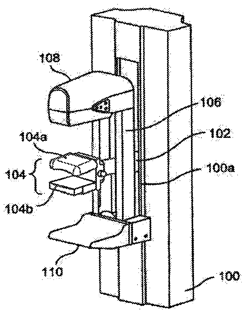
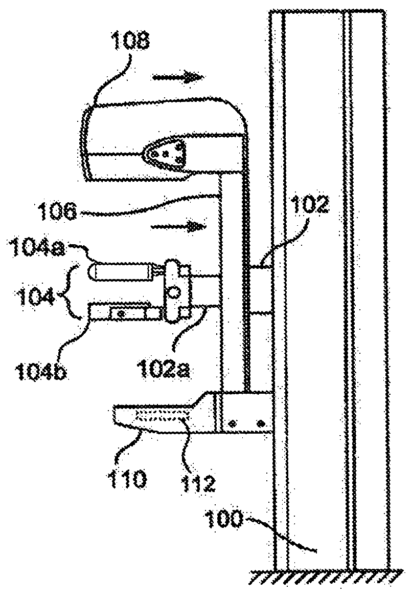
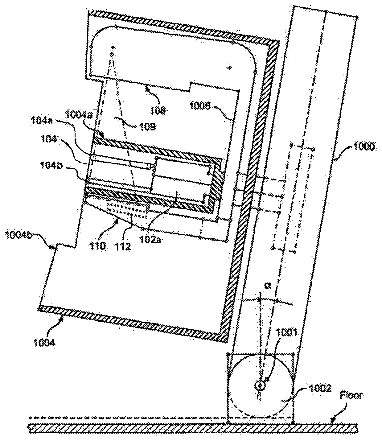
[0038] The technology relates to breast compression elements, such as breast compression paddles or compression support surfaces, for breast imaging systems. During breast imaging, it is often desirable to immobilize the breast with compression. For example, by compressing the breasts, the breasts can be thinned, requiring a lower dose of radiation. Additionally, by immobilizing the breast, image blurring due to movement of the breast during imaging is reduced. Other benefits can also be achieved through breast compression. However, the paddles commonly used to compress breasts can cause distortion during imaging because the X-rays must pass through the paddles. For example, although compression paddles are generally made of at least partially radiolucent materials, the shape and configuration of the compression paddles can deflect, refract, scatter, reflect, or otherwise undesirably interact with the X-ray beam as it passes through the paddle. interference. Consequently, ...


PUM

PropertyMeasurementUnit
Thicknessaaaaaaaaaa

Abstract

A curved compression element, such as a breast compression paddle, and imaging systems and methods for use with curved compression elements. A system may include a radiation source, a detector, and acurved compression element. Operations are performed that include receiving image data from the detector; accessing a correction map for the at least one compression paddle; correcting the image databased on the correction map to generate a corrected image data; and generating an image of the breast based on the corrected image data. The breast compression element generally has no sharp edges, but rather has smooth edges and transitions between surfaces. The breast compression paddle also includes a flexible material that spans a portion of a curved bottom surface of the breast compression paddle to define a gap. The flexible material may be a thin-film material such as a shrink wrap.

Description

[0001] Cross References to Related Applications [0002] This application was filed as a PCT International Application on September 25, 2017, and claims priority to: (1) U.S. Provisional Application No. 62 / 419,336, filed November 8, 2016, entitled "Breast Compression Paddle" , and (2) U.S. Provisional Application No. 62 / 531,807, filed July 12, 2017, entitled "Image Processing For Curved Paddles," both of which are incorporated by reference in their entirety. Background technique [0003] An important patient concern in mammography and breast tomosynthesis is that when the breast is compressed (usually between two rigid plastic surfaces with sufficient force to immobilize the breast and unfold the breast tissue for x-ray imaging) the patient will Feeling of discomfort. Another major challenge is ensuring that the imaging field includes the required amount of breast tissue. Reasons for using compression include: (1) to thin the breast in the direction of the X-ray flux, thereb...

Claims


Application Information

Patent Timeline
IPC IPC(8): A61B6/04A61B6/00B65B53/02
CPCA61B6/0414A61B6/4233A61B6/4423A61B6/4441A61B6/4447A61B6/4452A61B6/502A61B6/5258A61B6/582A61B6/4411A61B6/04A61B6/5252
Inventor 谌飚T·R·斯坦戈J·A·斯泰因C·鲁斯
Owner HOLOGIC INC
Why Eureka
Try Eureka