Eureka AIR delivers breakthrough ideas for toughest innovation challenges, trusted by R&D personnel around the world.

Imaging control apparatus, imaging control method, and imaging control program

a control apparatus and control method technology, applied in the field of imaging control apparatus, can solve the problems of deteriorating image quality, difficult to find abnormal parts, increased noise in projection images and even tomographic images, etc., and achieve the effect of appropriately setting the imaging mode of the breas

Pending Publication Date: 2021-12-23
FUJIFILM CORP
View PDF13 Cites 0 Cited by
  • Summary
  • Abstract
  • Description
  • Claims
  • Application Information

AI Technical Summary

Benefits of technology

The present disclosure is about a device that can appropriately set the imaging mode for breast imaging. The device can detect the volume and ratio of the breast and automatically select the appropriate imaging mode based on those parameters. It can also detect the thickness of the breast and select the appropriate imaging mode based on that information. By setting the imaging mode based on these parameters, the device can improve breast imaging quality and provide better diagnostic information.

Problems solved by technology

In a case of a breast in which a density of mammary gland is high, the abnormal portion may be hidden by the mammary gland in the breast image, and as a result, it may be difficult to find the abnormal portion.
On the other hand, in a case where the grid is not used, a noise in the projection image and even the tomographic image is increased due to an influence of the scattered radiation, and as a result, an image quality is deteriorated.
In particular, in a case of a patient with a thick breast, a degree of scattering of the radiation is increased, and this causes an increase of a noise caused by the scattered radiation.
As a result, even though tomosynthesis imaging is performed, it may be more difficult to detect an abnormal portion as compared with a simple two-dimensional image.
However, as described in JP2012-135444A, in the method based on the ratio of the area of the mammary gland region, an appropriate imaging mode may not be selected.

Method used


Image

  • Imaging control apparatus, imaging control method, and imaging control program
  • Imaging control apparatus, imaging control method, and imaging control program
  • Imaging control apparatus, imaging control method, and imaging control program

Examples


Embodiment Construction

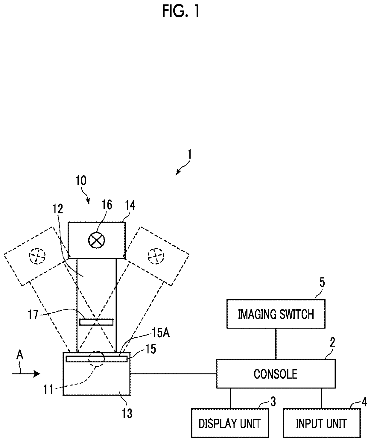
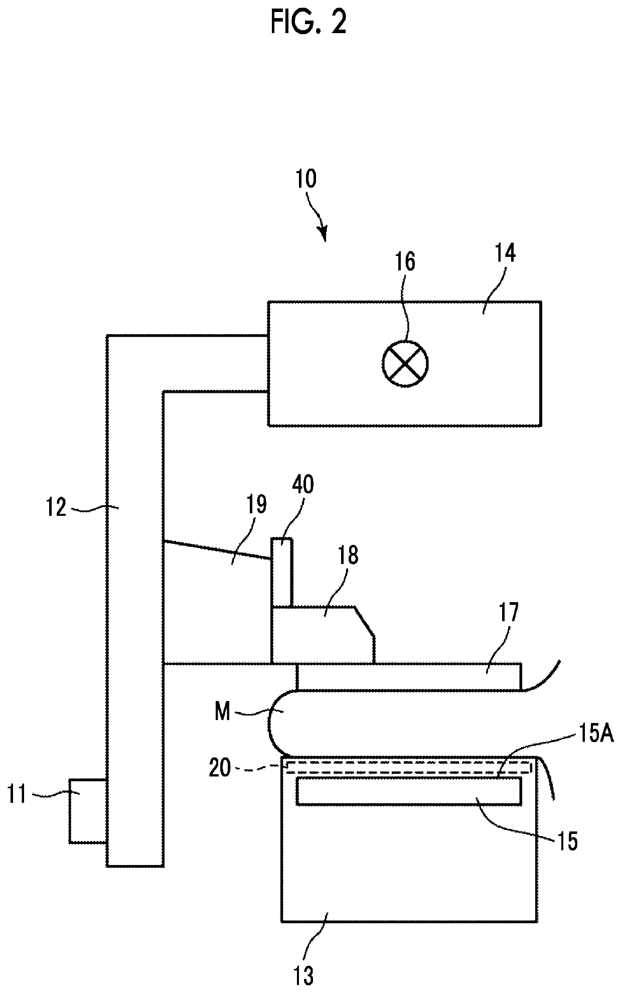
[0042]Hereinafter, embodiments of the present disclosure will be described with reference to the drawings. FIG. 1 is a schematic configuration diagram of a radiography system to which an imaging control apparatus according to an embodiment of the present disclosure is applied, and FIG. 2 is a diagram illustrating a mammography apparatus included in the radiography system as viewed from a direction of an arrow A in FIG. 1.

[0043]As illustrated in FIG. 1, a radiography system 1 according to the present embodiment includes a console 2 and a mammography apparatus 10. The console 2 includes a display unit 3, an input unit 4, and an imaging switch 5.

[0044]The radiography system 1 according to the present embodiment has a function of performing tomosynthesis imaging of a patient's breast by the mammography apparatus 10 and acquiring tomographic images of the breast on a plurality of tomographic planes, based on an instruction (imaging order) which is input from an external system (for examp...


PUM


Abstract

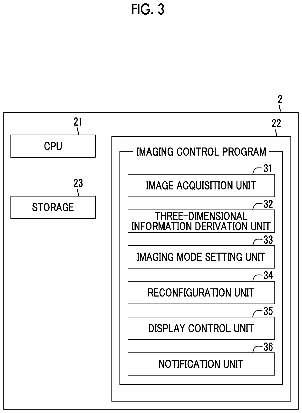
An image acquisition unit acquires a first breast image by imaging a breast which is being compressed by first imaging. A three-dimensional information derivation unit derives three-dimensional information of a mammary gland included in the first breast image. An imaging mode setting unit sets an imaging mode for second imaging of the breast based on the three-dimensional information. The image acquisition unit acquires a second breast image by imaging the breast without releasing a state during the first imaging where the breast is compressed by the second imaging based on the set imaging mode.

Description

CROSS-REFERENCE TO RELATED APPLICATIONS[0001]The present application is a Continuation of PCT International Application No. PCT / JP2019 / 044391, filed on Nov. 12, 2019, which claims priority to Japanese Patent Application No. 2019-060371, filed on Mar. 27, 2019. Each application above is hereby expressly incorporated by reference, in its entirety, into the present application.BACKGROUNDTechnical Field[0002]The present disclosure relates to an imaging control apparatus, an imaging control method, and an imaging control program.Related Art[0003]In recent years, in order to promote early detection of breast cancer, image diagnosis using a radiography apparatus (called mammography) that performs imaging of a breast has attracted attention. In mammography, the breast is placed on an imaging table, and imaging is performed in a state where the breast is being compressed by a compression plate. The breast mainly consists of mammary gland tissue and adipose tissue, and in image diagnosis, it ...

Claims


Application Information

Patent Timeline
Patent Type & Authority Applications(United States)
IPC IPC(8): A61B6/00G06T7/00G06K9/32A61B6/02
CPCA61B6/502G06T7/0012G06K9/3233G06T2207/30068A61B6/466A61B6/025A61B6/469A61B6/0414A61B6/463A61B6/545A61B6/488G06V10/25
Inventor MORITA, JUNYA
Owner FUJIFILM CORP
Why Eureka
Eureka Blog
Learn More