
Forming mould for flange forging and forging method

A technology for forming dies and forging, applied in the direction of manufacturing tools, forging/pressing/hammer devices, forging/pressing/hammering machinery, etc., can solve the problems of fast material flow, cracking or folding of forgings, etc.

Pending Publication Date: 2019-08-13
常州市丰乐精锻有限公司
View PDF0 Cites 5 Cited by
  • Summary
  • Abstract
  • Description
  • Claims
  • Application Information

AI Technical Summary

Problems solved by technology

[0004] The present invention solves the problem of cracking or folding after the forging is formed due to the fast fluidity of the material during forming and forging of the existing large flange, and thus provides a forming die and forging method for flange forging

Method used


Image

  • Forming mould for flange forging and forging method
  • Forming mould for flange forging and forging method

Examples


Embodiment Construction

[0022] In describing the present invention, it should be understood that the terms "center", "longitudinal", "transverse", "length", "width", "thickness", "upper", "lower", "front", " Back", "Left", "Right", "Vertical", "Horizontal", "Top", "Bottom", "Inner", "Outer", "Axial", "Radial", "Circumferential", etc. The indicated orientation or positional relationship is based on the orientation or positional relationship shown in the drawings, and is only for the convenience of describing the present invention and simplifying the description, rather than indicating or implying that the referred device or element must have a specific orientation, or in a specific orientation. construction and operation, therefore, should not be construed as limiting the invention.

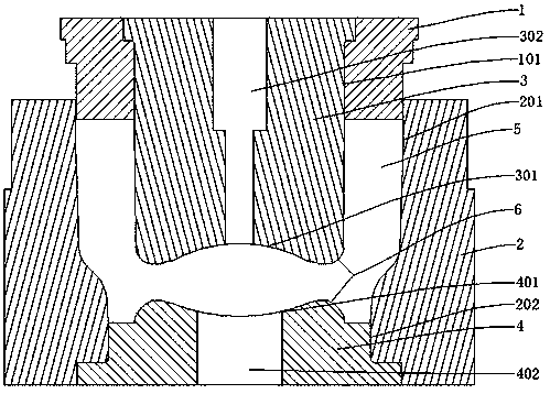
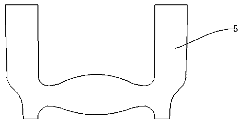
[0023] like figure 1 and figure 2 As shown, a forming die for flange forging includes a forming upper die 1 and a forming lower die 2, a forming chamber 201 is opened above the forming lower die 2, and the forming upp...


PUM


Abstract

The invention provides a forming mould for flange forging. The forming mould comprises a forming upper mould and a forging lower mould, wherein a forming bin is arranged above the forming lower mould;the forming upper mould is movably mounted in the forming bin; a lower mounting slot is formed in the bottom of the forming bin; the lower mounting slot penetrates through the lower surface of the forming lower mould; a lower mould core is embedded into the lower mounting slot; an upper mounting slot is formed in the forming upper mould in a penetrating mode; an upper mould core is mounted in theupper mounting slot; an upper groove is formed in the lower surface of the upper mould core; a lower groove is formed in the upper surface of the lower mould core; the upper groove and the lower groove are spherical arc-shaped slots; and the curvature of the arc surface of the upper grove is the same with that of the arc surface of the lower groove; the forming upper mould, the forming lower mould, the upper mould core and the lower mould core are closed to define a forming cavity; and the forming cavity is positioned in the upper groove and the lower groove to define a spherical cylindricalstructure. The forming mould solves the problem that an existing forming mould causes a formed forge piece to crack or fold as a result of a too great flange size and quick material flow, and is suitable for flanges with relatively great sizes.

Description

technical field [0001] The invention belongs to the technical field of flange forging die equipment, and in particular relates to a forming die for flange forging and a forging method. Background technique [0002] Flanges are also called flange flanges or flanges. Flanges are parts that are connected to each other between shafts and are used for connection between pipe ends; they are also useful for flanges on equipment inlets and outlets, used for two The connection between equipment, such as reducer flange, flange connection or flange joint, refers to the detachable connection of flanges, gaskets and bolts as a combined sealing structure. Pipe flange refers to The flange used for piping in the pipeline installation refers to the inlet and outlet flanges of the equipment used in the equipment. There are holes on the flange, and the bolts make the two flanges tightly connected. The gasket is used to seal the flanges. The flanges are divided into threaded connections. Flang...

Claims


Application Information

Patent Timeline
IPC IPC(8): B21K1/32B21J13/02B21J5/00
CPCB21J5/002B21J13/02B21K1/32
Inventor 杨晓军
Owner 常州市丰乐精锻有限公司
Learn More