Slag falling system of garbage boiler

A technology for boilers and slag removal, applied in incinerators, combustion types, combustion methods, etc., can solve the problems of poor slag moving ability, increasing the difficulty of slag removal, and clogging of slag openings.

Inactive Publication Date: 2013-11-27
南通万达能源动力科技有限公司
View PDF7 Cites 3 Cited by
  • Summary
  • Abstract
  • Description
  • Claims
  • Application Information

AI Technical Summary

Problems solved by technology

[0002] Due to the structural design of the slag removal device of the existing garbage incinerator, sometimes dense columnar hoods or mushroom-shaped hoods are arranged around the slag outlet. The accumulation and blockage at the slag outlet increases the difficulty of slag removal; there is also a single row of horizontal directional air caps near the slag outlet, and the columnar air caps on the outer side are dense. This structure solves the problem of poor slag fluidity. , the slag flow space is small, and it is easy to cause the winding and pulling of the iron wire, which affects the stable operation of the boiler; the above-mentioned slag removal devices only consider the movement of the slag to the slag outlet and do not consider the problem of the slag entering the slag outlet, and the existing garbage The pre-treatment of waste into the furnace is simple, and the slag after co-firing is not flowing smoothly, and it is easy to form large pieces of molten slag, which will cause blockage of the slag outlet

Method used


Image

  • Slag falling system of garbage boiler
  • Slag falling system of garbage boiler

Examples


Embodiment Construction

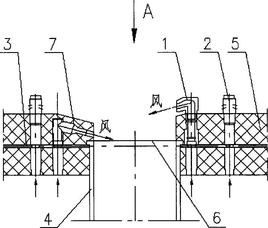
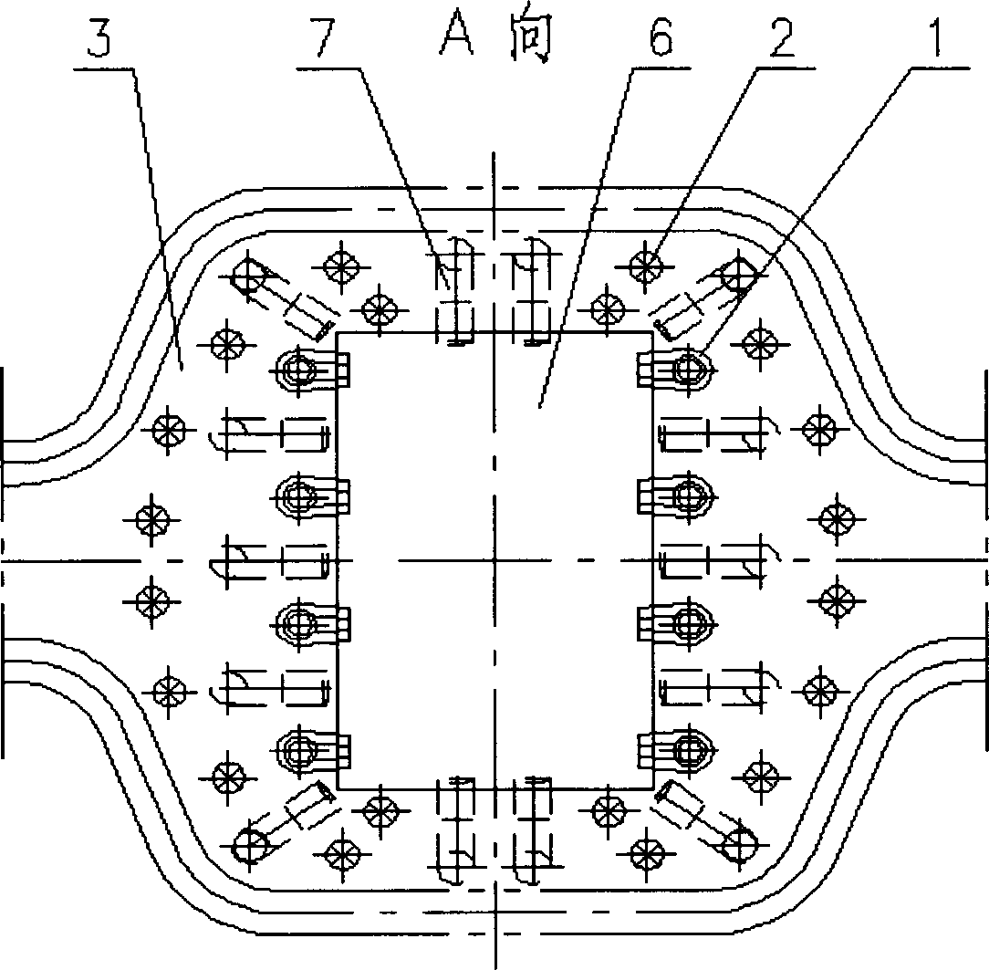
[0014] A garbage boiler slag removal system, comprising a square mouth directional air cap 1, a mushroom-shaped air cap 2, an air distribution plate 3, a slag removal pipe 4, a pouring material 5, and a slag outlet 6, and is characterized in that it also includes a duckbill-shaped directional air cap 7. Duckbill-shaped directional hood 7, square-mouth directional hood 1, and mushroom-shaped hood 2 are layered on the outside of the slag outlet 6 from inside to outside. The position near the slag outlet 6 forms a stepped shape with an up and down drop. The mushroom-shaped hood 2 is arranged outside the slag outlet, and the duckbill-shaped directional hood 7 is completely buried in the castable 5. Type hoods 2 stretch out from the surface of castable 5, and all hoods are vertically inserted into the openings of the air distribution plate 3.

[0015] The shape of the air outlet of the duckbill-shaped directional air cap 7 is oblate, similar to a duckbill, and the downward inclinat...


PUM


Abstract

The invention discloses a slag falling system of a garbage boiler. The slag falling system comprises a square-opening directional hood, a columnar hood or a mushroom-type hood, an air distributing plate, a slag falling pipe, a casting material and a slag outlet and also comprises a duckbill-type directional hood, wherein the duckbill-type directional hood, the square-opening directional hood and the mushroom-type hood are distributed on the outer side of the slag outlet from inside to outside in a layered manner; the square-opening directional hood and the duckbill-type directional hood are distributed at the near position close to the slag outlet at an interval in a staggering manner and form a step shape with up-down fall; the mushroom-type hood is distributed on the outer side of the slag outlet; the duckbill-type directional hood is completely buried in the casting material, while the square-opening directional hood and the mushroom-type hood extend out of the surface of the casting material; all the hoods are vertically inserted into opened holes of the air distributing plate. The slag falling system disclosed by the invention has the beneficial effects that the duckbill-type directional hood, the square-opening directional hood and the mushroom-type hood are combined and distributed, so that the flowing space of furnace slag is enlarged, the winding probability of iron wires at a slag falling port is reduced, the fluidization air quantity of the outlet is increased, and the whole device is beneficial to forming good working condition with uniform fluidization and disturbance at the upper part and smooth drainage and deslagging at the lower part.

Description

Technical field: [0001] The invention relates to a slag dropping system in the technical field of garbage incineration boiler equipment. Background technique: [0002] Due to the structural design of the slag removal device of the existing garbage incinerator, sometimes dense columnar hoods or mushroom-shaped hoods are arranged around the slag outlet. The accumulation and blockage at the slag outlet increases the difficulty of slag removal; there is also a single row of horizontal directional air caps near the slag outlet, and the columnar air caps on the outer side are dense. This structure solves the problem of poor slag fluidity. , the slag flow space is small, and it is easy to cause the winding and pulling of the iron wire, which affects the stable operation of the boiler; the above-mentioned slag removal devices only consider the movement of the slag to the slag outlet and do not consider the problem of the slag entering the slag outlet, and the existing garbage The p...

Claims


Application Information

Patent Timeline
Patent Type & Authority Applications(China)
IPC IPC(8): F23G5/44
Inventor 茅素梅刘宝鑫徐获萍茅正东蔡永祥陆子龙黄卫冲成星星王沈兵陈俊
Owner 南通万达能源动力科技有限公司
Why Eureka
Try Eureka