Tunnel type drying device

A drying device and tunnel-type technology, which is applied in the field of tunnel-type drying devices, can solve problems such as excessive heat, poor drying effect, and affecting the heat utilization rate of the drying furnace, and achieve the effect of increasing the speed

Inactive Publication Date: 2013-10-16
CHONGQING POLYCOMP INT
View PDF3 Cites 3 Cited by
  • Summary
  • Abstract
  • Description
  • Claims
  • Application Information

AI Technical Summary

Problems solved by technology

Because the hot air mixes with the cold air in the hot air channel at the top of the drying chamber before entering the drying chamber, a large amount of heat will be dissipated to the outside air through the top plate of the furnace body, which will affect the heat utilization rate of the drying furnace. , the drying effect is poor
At the same time, due to the narrow space of the cavity of the existing tunnel-type drying furnace, the hot air cannot flow well in the cavity of the drying furnace after the hot air is introduced, and it needs to consume more heat and time to complete the glass drying process. The drying of fibers further affects the heat utilization rate and drying efficiency

Method used


Image

  • Tunnel type drying device
  • Tunnel type drying device
  • Tunnel type drying device

Examples


Embodiment Construction

[0024] The following will clearly and completely describe the technical solutions in the embodiments of the present invention with reference to the accompanying drawings in the embodiments of the present invention. Obviously, the described embodiments are only some, not all, embodiments of the present invention. Based on the embodiments of the present invention, all other embodiments obtained by persons of ordinary skill in the art without making creative efforts belong to the protection scope of the present invention.

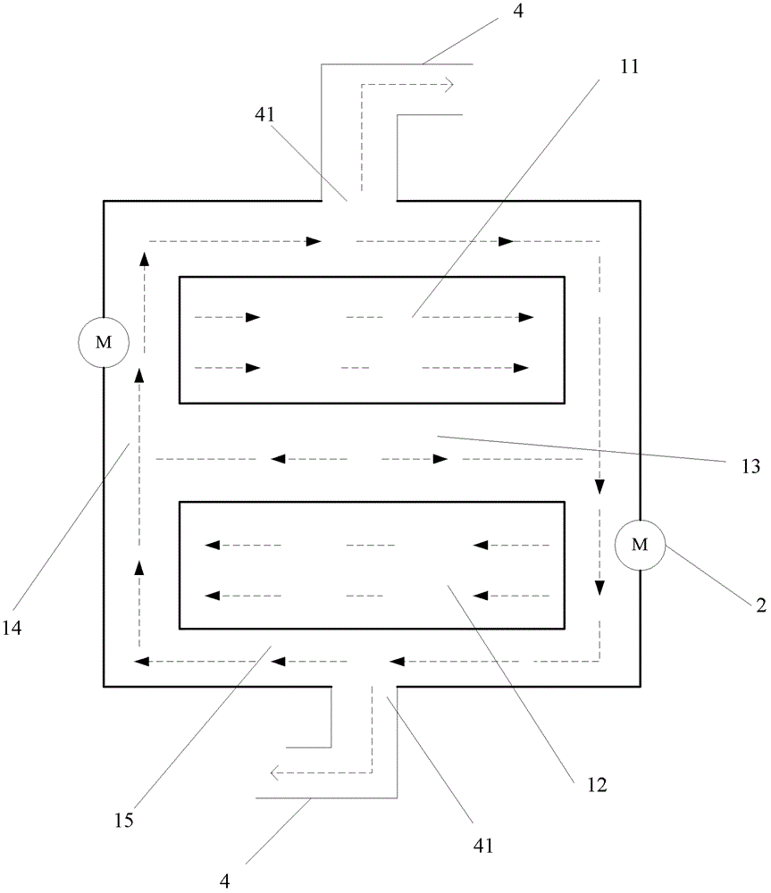
[0025] see figure 1 , shows a schematic structural view of an embodiment of a tunnel drying device of the present invention, the drying device includes: a furnace body, a hot air supply system, a hot air supply pipeline, a dehumidifier, and a dehumidifier connected to the dehumidifier Dehumidifier duct. The number of furnace bodies included in the tunnel drying device can be one or more. This figure is a schematic cross-sectional view of a furnace body. The p...


PUM


Abstract

The invention discloses a tunnel type drying device, which comprises a furnace body, a hot air supply system, a hot air supply pipeline, a dehumidifying fan and a dehumidifying pipeline, wherein a first drying cavity and a second drying cavity are formed in the furnace body; the first drying cavity is positioned over the second drying cavity; a suspension interlayer is formed between a bottom plate of the first drying cavity and a top plate of the second drying cavity; a vertical hot air channel is formed between the side walls of the first drying cavity and the second drying cavity and the side wall of the furnace body; the vertical hot air channel is communicated with the suspension interlayer; horizontal hot air channels are formed between a top plate of the first drying cavity and a top plate of the furnace body as well as between a bottom plate of the second drying cavity and a bottom plate of the furnace body; the horizontal hot air channels are communicated with the vertical hot air channel; the hot air outlet of the hot air supply pipeline is formed in the suspension interlayer; and hot air is output from the hot air outlet. By adopting the drying device, hot air can flow better in the drying process, and the drying efficiency is increased on the premise of lowering the hot energy consumption.

Description

technical field [0001] The invention relates to the technical field of glass fiber drying, in particular to a tunnel drying device. Background technique [0002] Glass fiber is an inorganic non-metallic material with excellent performance. It is made of glass balls or waste glass through high-temperature melting and wire drawing. Glass fiber has the advantages of good insulation, high heat resistance, and corrosion resistance, and is widely used in various fields. [0003] Some sizing agent emulsions are used in the process of making glass fibers. In order to solidify the sizing agent into a film and remove excess water in the drawn glass fibers, it is necessary to dry the drawn glass fibers. In the existing single-layer tunnel-type drying furnace for drying glass fibers, a drying cavity is built into the furnace body of the drying furnace. The bottom of the drying cavity is provided with yarn car tracks, and the yarn loaded with glass fibers The car enters the drying cham...

Claims


Application Information

Patent Timeline
Patent Type & Authority Patents(China)
IPC IPC(8): C03C25/16
Inventor 张聪
Owner CHONGQING POLYCOMP INT
Why Eureka
Try Eureka