Transmission shaft

A technology of transmission shaft and No. 1, applied in the field of transmission shaft, can solve the problems affecting the printing of printed products, surface roughness, technical scheme limitation, etc., and achieve the effect of improving the effect and improving the service life.

Active Publication Date: 2019-08-13
欧伯朗精工(江苏)有限公司
View PDF5 Cites 2 Cited by
  • Summary
  • Abstract
  • Description
  • Claims
  • Application Information

AI Technical Summary

Problems solved by technology

[0003] In the prior art, there is a shaft for printing printed products. In printing, one side of the shaft is first immersed in ink, and the ink will adhere to the outer peripheral surface of the shaft. Printing on printed products; however, after the printing of printed products is completed

Method used


Image

  • Transmission shaft
  • Transmission shaft
  • Transmission shaft

Examples


Example Embodiment

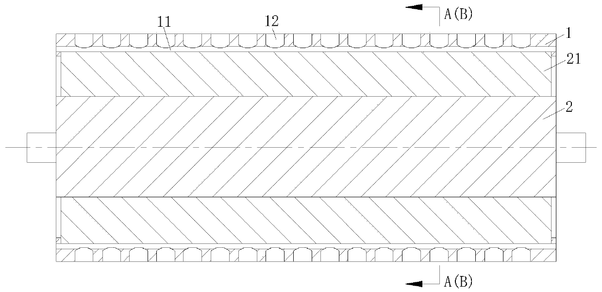
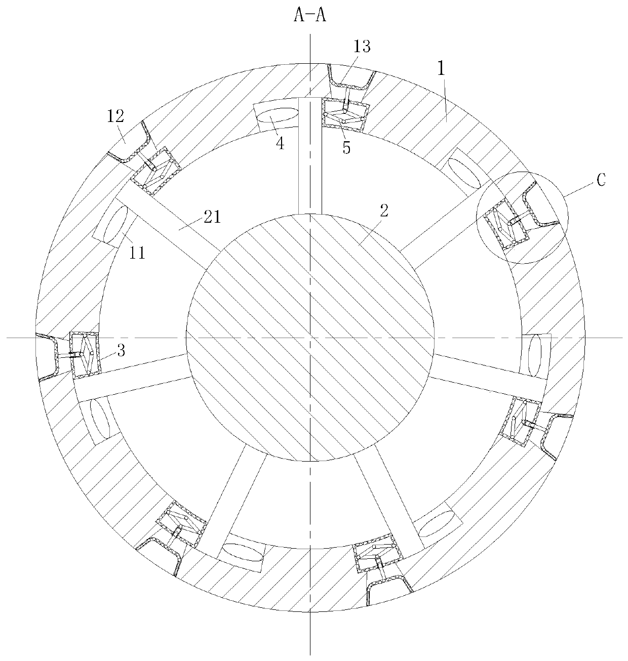
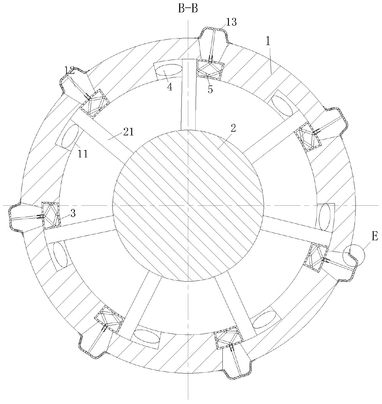
[0027] As a specific embodiment of the present invention, the first hole 131 is an oblique hole; through the oblique first hole 131, it is convenient for gas to clean impurities on the outer ring of the outer shaft 1; the present invention adopts this design, The gas is accurately blown to the outer ring of the outer shaft 1 to clean the remaining material on the outer ring of the outer shaft 1, thereby improving the cleaning effect of the drive shaft.

Example Embodiment

[0028] As a specific implementation of the present invention, the elastic sheet 13 is provided with a first slot 132, the first slot 132 is provided with a cleaning block 133, and the first slot 132 communicates with the first hole 131; the cleaning block 133 It is fixedly connected to the side wall of the first slot 132 by a spring. In the initial state, the cleaning block 133 is located in the first slot 132; the cleaning block 133 increases the cleaning of impurities on the outer ring of the outer shaft 1; when the elastic sheet 13 is deformed and turned over , Due to gravity, the cleaning block 133 will slide out of the No. 1 slot 132. When the cleaning block 133 slides out of the No. 1 slot 132, it will clean up the remaining material on the outer ring of the outer shaft 1, thereby improving the cleaning effect on the drive shaft; When the elastic piece 13 loses the function of gas, the elastic piece 13 returns to its original shape, and the cleaning block 133 returns to th...


PUM


Abstract

The invention belongs to the technical field of shafts, and particularly relates to a transmission shaft. An outer shaft and an inner shaft are included. The interior of the outer shaft is of a cavitystructure, and the inner shaft is inserted and connected in the outer shaft. Rotation grooves are evenly formed in the inner cavity wall of the outer shaft, rotation plates are evenly arranged on theouter wall of the inner shaft, the rotation plates are rotationally inserted and connected in the rotation grooves, one sides of the rotation plates are connected to the side walls of the rotation grooves through elastic seal bags, and the other side faces of the rotation plates are connected to the other side walls of the rotation grooves through air bags. The outer shaft is evenly provided witha set of gas blowing ports, and the gas blowing ports are located above the elastic seal bags. When the outer shaft continuously rotates due to inertia, the rotation plates can extrude the elastic seal bags, meanwhile, gas generated by the elastic seal bags is controlled to be blown out of the gas blowing ports, accordingly, printing materials left on an outer shaft outer ring after printing product printing are cleaned, the situation that when the transmission shaft is used for printing a printing product in the later period, the printing quality of the printing product is influenced is avoided, and accordingly, the practicability of the transmission shaft is improved.

Description

technical field [0001] The invention belongs to the technical field of shafts, in particular to a transmission shaft. Background technique [0002] The shaft (shaft) is a cylindrical object that goes through the middle of the bearing or the middle of the wheel or the middle of the gear, but there are also a few of them that are square. A shaft is a mechanical part that supports and revolves with a rotating part to transmit motion, torque or bending moment. [0003] In the prior art, there is a shaft for printing printed products. In printing, one side of the shaft is first immersed in ink, and the ink will adhere to the outer peripheral surface of the shaft. Printing on printed products; however, after the printing of printed products is completed, there are still residues on the outer ring of the shaft. If the residues are not cleaned up, the surface of the shaft will be damaged under the action of post-printing pressure and heat. It becomes rough and affects the printing...

Claims


Application Information

Patent Timeline
IPC IPC(8): B41F13/10B41F35/02F16C3/02
CPCB41F13/10B41F35/02F16C3/02
Inventor 周宇凡常康华李的根
Owner 欧伯朗精工(江苏)有限公司
Why Eureka
Try Eureka