Automatic gluing device

A glue coating device and automatic technology, which is applied to the surface coating liquid device, spray device, coating, etc., can solve the problems of robot use danger, tilt or fall, and safety hazards, so as to reduce the difficulty of use and improve The effect of stability and accuracy improvement

Pending Publication Date: 2019-08-16
广州信邦智能装备股份有限公司
View PDF0 Cites 2 Cited by
  • Summary
  • Abstract
  • Description
  • Claims
  • Application Information

AI Technical Summary

Problems solved by technology

[0002] The automatic gluing device is a device that uses a robot to apply glue to the joints of the car frame. However, with the development of science and technology, people have higher and higher requirements for the automatic gluing device. As a result, the traditional automatic gluing device can no longer meet the requirements. people's needs;
[0003] The existing automatic gluing device has certain defects when in use, (1), the rubber coating tube at the front end of the automatic gluing device is exposed, and when not in use, the primer of the rubber coating tube and the inside of the rubber coating tube cannot be protected. Make the outside dust adhere to the surface of the primer through the air flow, which will affect the viscosity and stability of the primer after use, and it is prone to certain safety hazards; (2), when the existing automatic glue application device is in use, it needs a robot to drive the glue The gun moves back and forth. When the glue gun is extended, the center of gravity of the robot moves to the direction in which the glue gun is extended. It is a fall, which brings certain dangers to the use of the robot. Secondly, because the robot base is fixed to the ground, when the center of gravity of the robot moves forward, it will exert pressure on the front end of the base. Since the base is fixed to the ground, the rear end cannot be lifted. It is in a stretched state. When the center of gravity of the robot moves backwards, pressure is applied to the rear end of the base, and the front end is in a stretched state. Bending and stretching back and forth for a long time can easily and quickly reach the fatigue strength of the metal, resulting in breakage etc.; (3), when the existing automatic gluing device is in use, the robot mobilizes the base to move back and forth, so that the base slightly shakes, and when the base rocks, the bolts on the base can be mobilized to shake together. The base slides relative to each other, thereby rotating out of the base, which affects the safety of the robot and is easy to cause certain dangers. For this reason, we propose an automatic gluing device

Method used


Image

  • Automatic gluing device
  • Automatic gluing device
  • Automatic gluing device

Examples


Embodiment Construction

[0030] In order to make the technical means, creative features, goals and effects achieved by the present invention easy to understand, the present invention will be further described below in conjunction with specific embodiments.

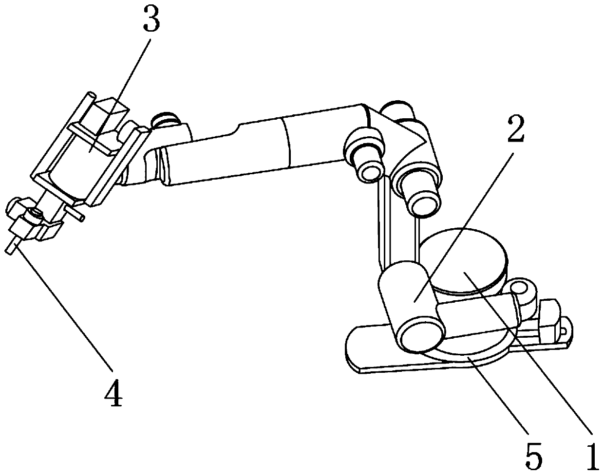
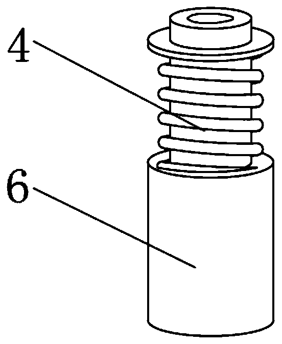
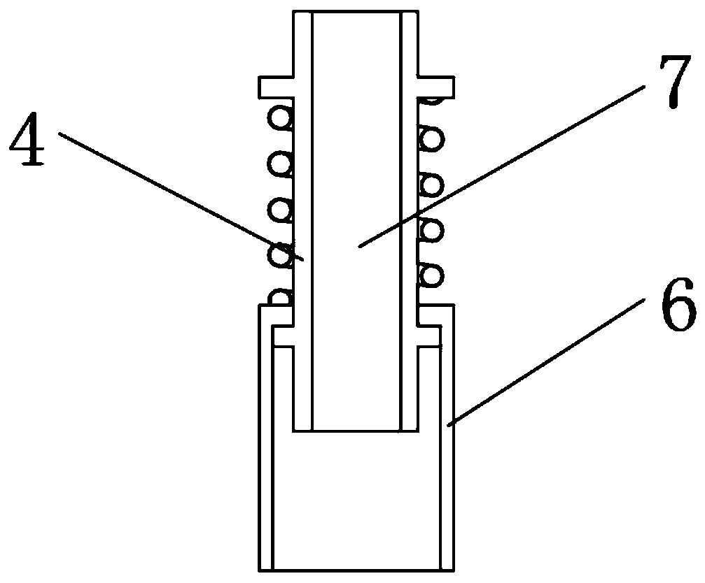
[0031] refer to figure 1 and Figure 4-7 As shown, an automatic gluing device includes a turret 1, a robot 2 is fixedly installed on the outer surface of the turret 1, and a glue gun 3 is provided at the end of the robot 2 away from the turret 1, and the bottom end of the glue gun 3 is fixedly installed There is a glue coating tube 4, the outer surface of the turret 1 is covered with a protective frame 5 near the bottom end, and the outer surface of the bottom end of the protective frame 5 is welded with a rotating low ring 8, and the outer surface of the rotating low ring 8 is welded respectively near the two sides. There is an extension plate 9 and a guide plate 10, and the top outer surface of the guide plate 10 is welded with a drive box 11 n...


PUM


Abstract

The invention discloses an automatic gluing device. The automatic gluing device comprises a rotating frame; a robot is fixedly mounted on the outer surface of the rotating frame; a glue gun is arranged at the end, far from the rotating frame, of the robot; and a gluing pipe is fixedly mounted at the bottom end of the glue gun. In the automatic gluing device, the outer surface of the gluing pipe issleeved with a protective cylinder through a spring for protecting bottom glue when the gluing pipe is not used to prevent pollution ofexternal dustto the bottom glue in the gluing pipe; an extensionplate is welded on the outer surface of the front end of a protecting frame for improving the use stability of the robot; a lead block capable of freely moving is mounted at the top end of a guide plate for assistingthe robot in adjustment of overall balanceto further improve the use stability of the robot; and after a fixed bolt is fixed, the fixed bolt is sleeved with a bolt sleeve from the topend of the fixed bolt, so that a bolt at the bottom end of the bolt sleeve is inserted in a pin groove to finish limiting of the bolt.

Description

technical field [0001] The invention relates to the field of automobile processing, in particular to an automatic gluing device. Background technique [0002] The automatic gluing device is a device that uses a robot to apply glue to the joints of the car frame. However, with the development of science and technology, people have higher and higher requirements for the automatic gluing device. As a result, the traditional automatic gluing device can no longer meet the requirements. people's needs; [0003] The existing automatic gluing device has certain defects when in use, (1), the rubber coating tube at the front end of the automatic gluing device is exposed, and when not in use, the primer of the rubber coating tube and the inside of the rubber coating tube cannot be protected. Make the outside dust adhere to the surface of the primer through the air flow, which will affect the viscosity and stability of the primer after use, and it is prone to certain safety hazards; (2...

Claims


Application Information

Patent Timeline
Patent Type & Authority Applications(China)
IPC IPC(8): B05C5/02B05B15/50B25J11/00B25J9/16
CPCB05B15/50B05C5/0208B25J9/1656B25J11/0075
Inventor 陈集成
Owner 广州信邦智能装备股份有限公司
Why Eureka
Try Eureka