
Clamping mechanism

A technology of clamping mechanism and clamping part, which is applied in the field of tools, can solve the problems of affecting the processing accuracy of workpieces, unstable clamping, inability to quickly clamp and lock, etc., to achieve the effect of ensuring stability and improving processing accuracy

Inactive Publication Date: 2019-08-16
POSITEC POWER TOOLS (SUZHOU) CO LTD
View PDF5 Cites 0 Cited by
  • Summary
  • Abstract
  • Description
  • Claims
  • Application Information

AI Technical Summary

Problems solved by technology

However, most of its clamping adopts screw nut structure, which cannot be quickly clamped and locked.
In addition, when clamping a workpiece with a long dimension (perpendicular to the direction of movement of the movable jaw), the size of the support surface provided by the bench vise (actually the upper surface of the guide rail) is small, which is prone to unstable clamping The problem, which affects the machining accuracy of the workpiece

Method used


Image

  • Clamping mechanism
  • Clamping mechanism
  • Clamping mechanism

Examples


Embodiment Construction

[0038] The detailed description and technical content of the present invention are as follows with the accompanying drawings, and the attached drawings are only for reference and description, and are not intended to limit the present invention.

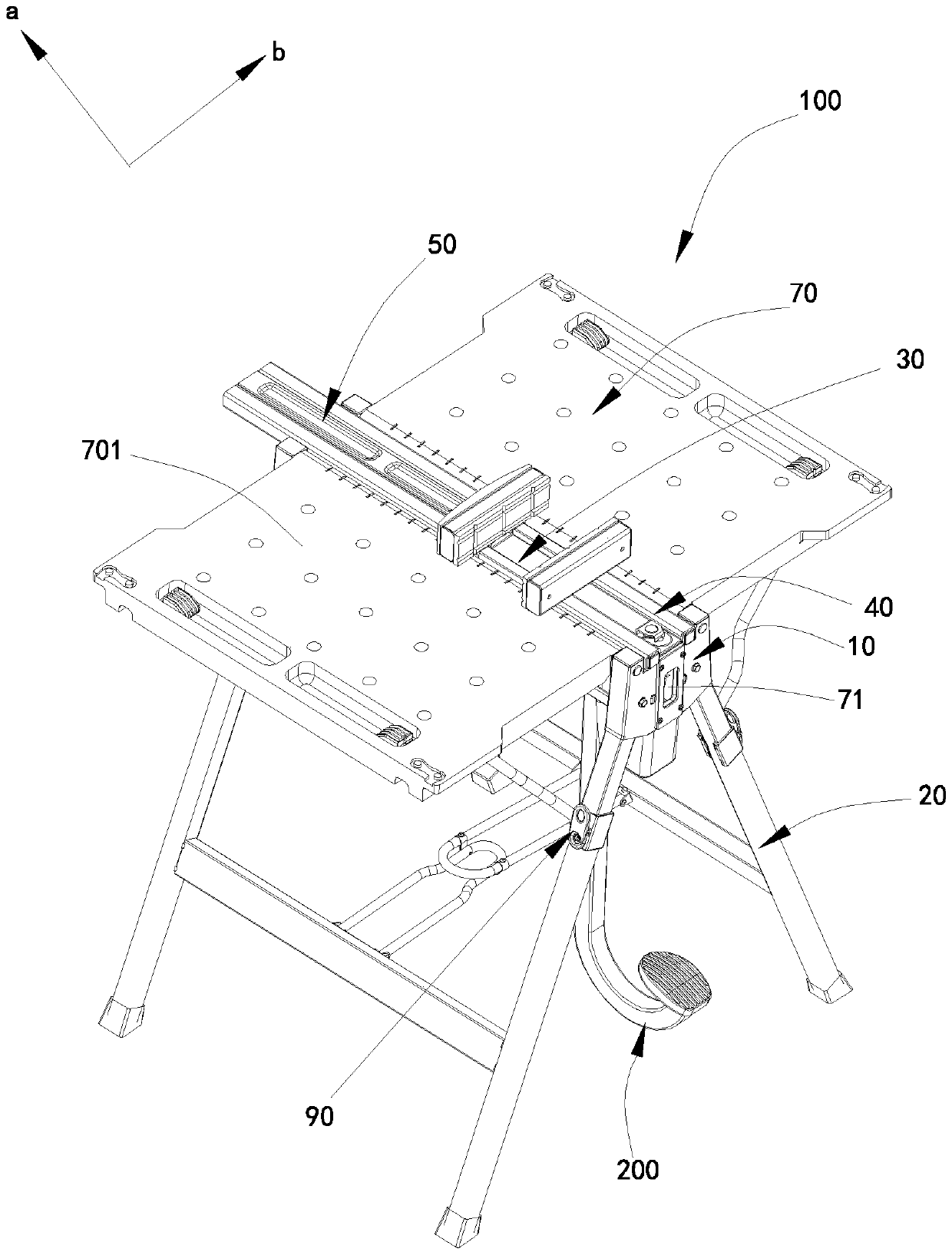
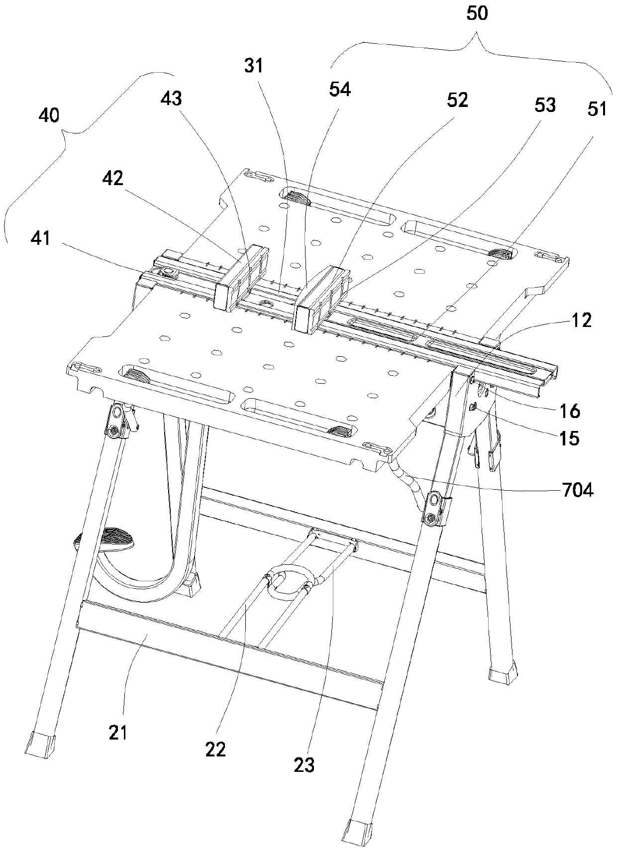
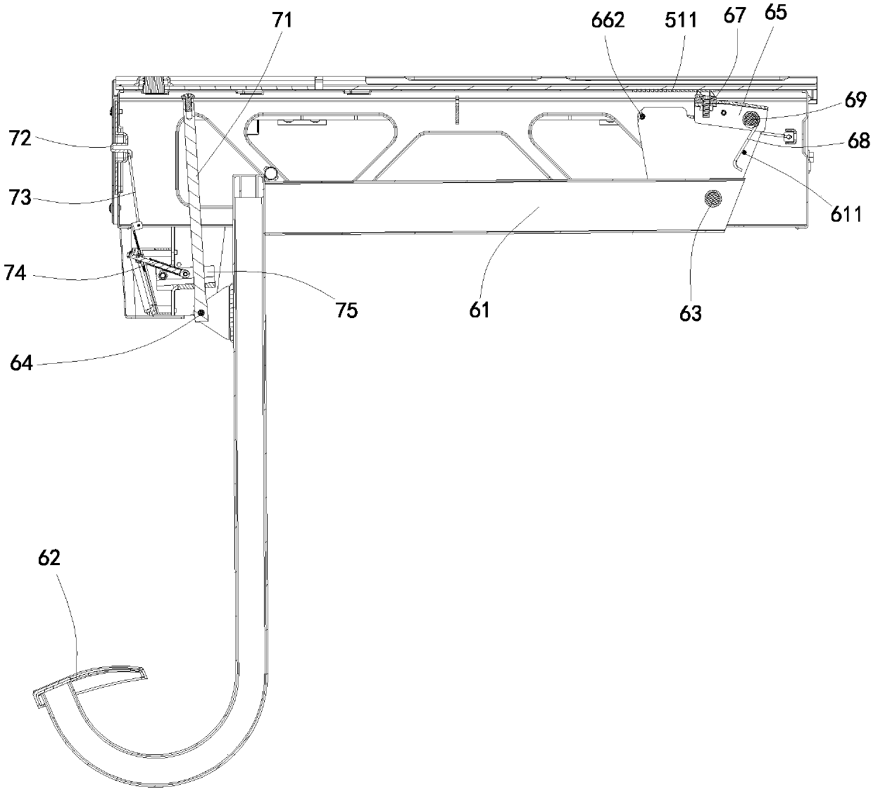
[0039] Figure 1 to Figure 11 The clamping mechanism 100 provided by the embodiment of the present invention is shown.

[0040] Please see figure 1 , the clamping mechanism 100 is used for clamping a workpiece (such as wood, sheet metal, etc.), so as to process, cut, grind and other operations on the workpiece. combine Figure 1 to Figure 2 , in this embodiment, the clamping mechanism 100 includes a base 10, a plurality of support legs 20 connected to the bottom of the base 10 and supporting the base, a fixed guide rail 30 fixed to the base, and a first clamp arranged on the fixed guide rail. The holding assembly 40, the second holding assembly 50 arranged on the fixed guide rail and the driving mechanism 200 for driving the second...


PUM


Abstract

A clamping mechanism comprises a base, a plurality of supporting legs, a fixed guide rail, a first clamping part, a second clamping part and a driving mechanism, wherein the multiple supporting legs are connected with the base in a matched mode and support the base; the fixed guide rail is arranged on the base and is provided with a first surface opposite to the supporting legs; the first clampingpart is arranged on the fixed guide rail; the second clamping part is movably arranged on the fixed guide rail; and the driving mechanism drives the second clamping part to move towards the first clamping part in the direction close to the first clamping part so that a workpiece can be clamped. The clamping mechanism further comprises a workbench connected to the base. The workbench is provided with a working surface. The workbench can move between a working position and a non-working position. When the workbench is in the working position, the working surface is not lower than the first surface and is used for supporting the workpiece; and when the workbench is in the non-working position, the working surface is not higher than the first surface. The clamping mechanism provided by the invention is provided with an auxiliary supporting face, the workpiece is clamped through the first clamping part and the second clamping part, large-sized workpieces can be better supported through theauxiliary supporting face provided by the workbench, and clamping stability is guaranteed.

Description

technical field [0001] The invention relates to the field of tools, in particular to a clamping mechanism. Background technique [0002] The traditional bench vise is installed on the fitter's table, and the movable jaw that can slide along the guide rail moves relative to the fixed jaw, so as to clamp the workpiece to be processed, which is convenient for the fitter to file, saw, etc. the workpiece manually or mechanically. However, most of its clamping adopts a screw nut structure, which cannot be quickly clamped and locked. In addition, when clamping a workpiece with a long dimension (perpendicular to the direction of movement of the movable jaw), the size of the support surface provided by the bench vise (actually the upper surface of the guide rail) is small, which is prone to unstable clamping The problem, thus affecting the machining accuracy of the workpiece. [0003] To overcome the above problems, a new clamping mechanism must be developed. Contents of the inve...

Claims


Application Information

Patent Timeline
Patent Type & Authority Applications(China)
IPC IPC(8): B25H1/02B25H1/08B25H1/10
CPCB25H1/02B25H1/08B25H1/10B27C9/00
Inventor 沃伦·布朗格雷厄姆·格哈德哈利·索默
Owner POSITEC POWER TOOLS (SUZHOU) CO LTD
Learn More