
Separable magnetic positioning joint, rotating structure and mechanical device

A magnetic positioning and rotating structure technology, applied in the direction of manipulators, manufacturing tools, joints, etc., can solve the problems of complex disassembly, difficult precise positioning, limited rotation range of positioning joints, etc.

Pending Publication Date: 2019-08-16
王雪龙 +1
View PDF0 Cites 0 Cited by
  • Summary
  • Abstract
  • Description
  • Claims
  • Application Information

AI Technical Summary

Problems solved by technology

[0003] For this reason, the embodiment of the present invention provides a detachable magnetic positioning joint, a rotating structure and mechanical equipment to solve the problem of limited rotation range of positioning joints in the prior art, difficulty in precise positioning after wear and tear, complex disassembly, low pose accuracy, and stability sex problem

Method used


Image

  • Separable magnetic positioning joint, rotating structure and mechanical device
  • Separable magnetic positioning joint, rotating structure and mechanical device
  • Separable magnetic positioning joint, rotating structure and mechanical device

Examples


Embodiment 1

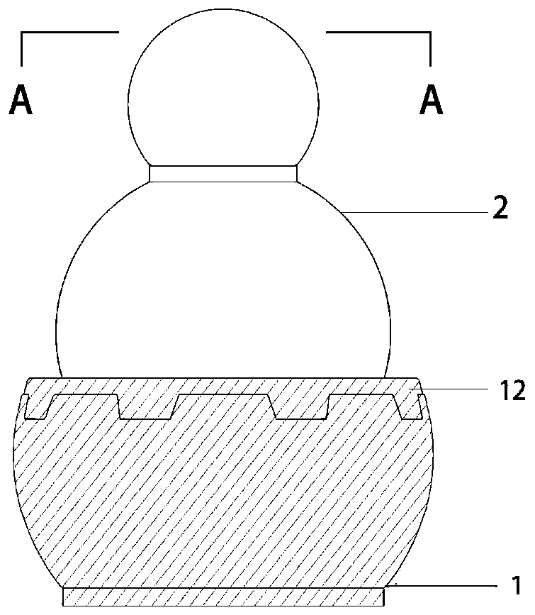
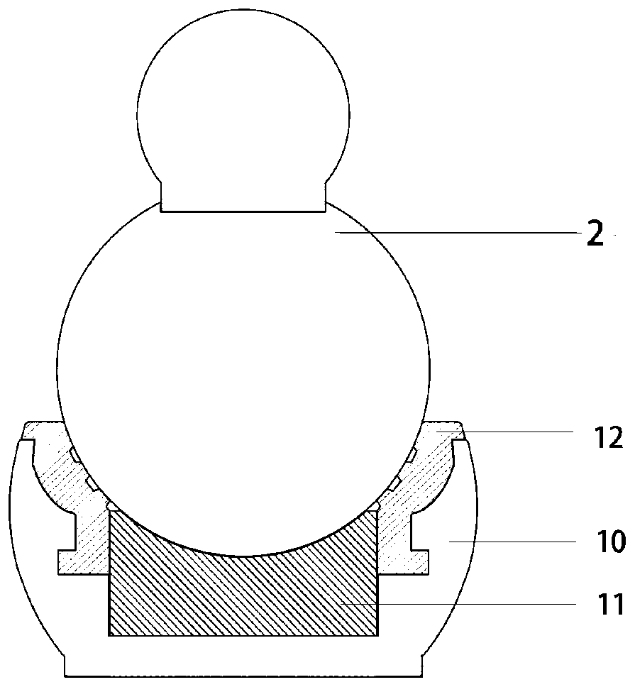
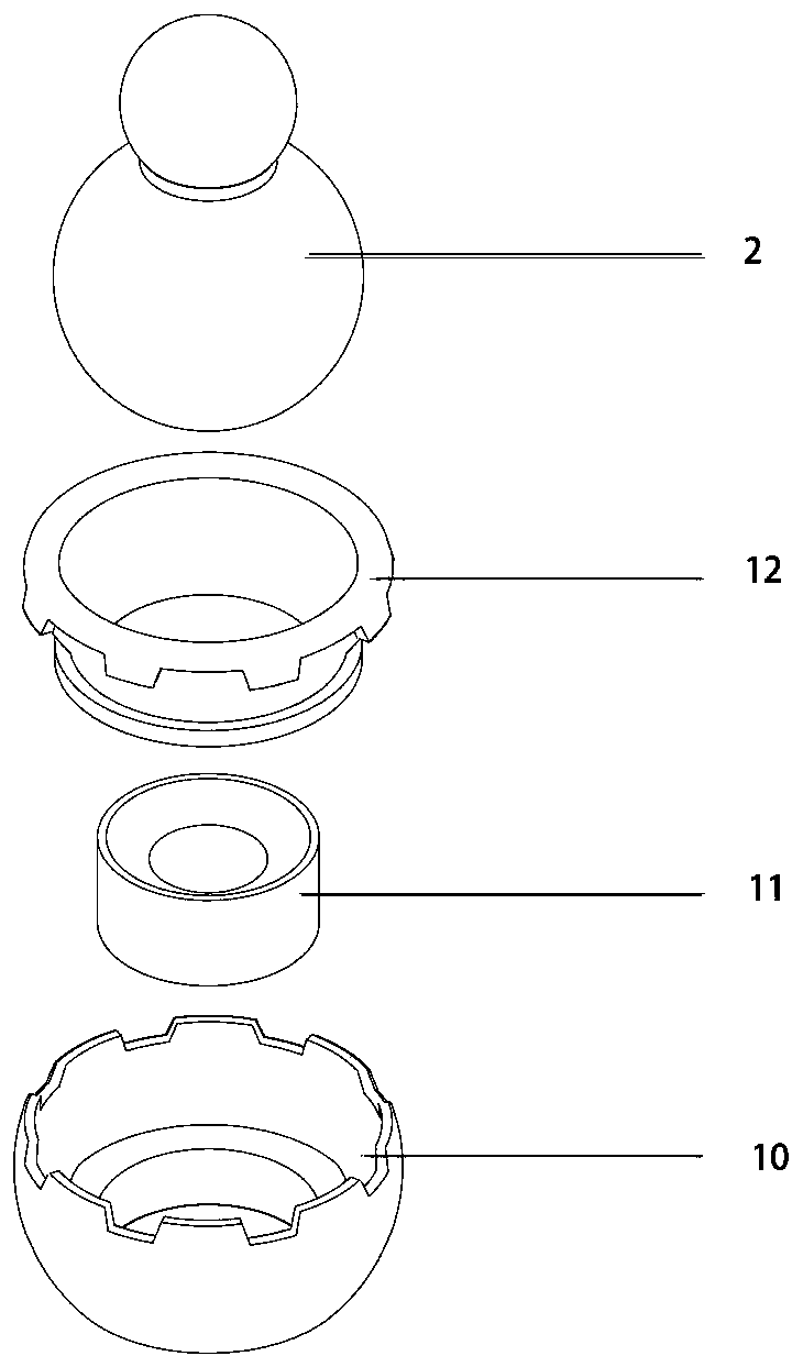
[0042] According to the first aspect of the embodiment of the present invention, a detachable magnetic positioning joint 100 is provided, such as Figure 1-3 As shown, the joint base 1 and the joint head 2 are included, the joint head 2 is magnetically connected with the joint base 1; the joint base 1 includes the joint base body 10, and the joint base 1 also includes one or more positioning damping bodies 12 and / or one or more a magnetic damping body 11; when the joint base 1 includes at least a magnetic damping body 11, the joint base body 10 contacts the joint head 2 through the magnetic damping body 11; when the joint base 1 includes at least a positioning damping body 12, the joint base body 10 passes through Position the damping body 12 in contact with the joint head 2 .

[0043] In this embodiment, the following three situations are included:

[0044] When the joint base 1 only includes the magnetic damping body 11, the joint base body 10 contacts the joint head 2 thro...

Embodiment 2

[0059] According to the first aspect of the embodiment of the present invention, another detachable magnetic positioning joint 100 is provided, such as Figure 4-6 As shown, it includes the joint base 1 and the joint head 2, the joint head 2 is magnetically connected with the joint base 1; the joint base 1 includes the joint base body 10, the joint base magnetic cover 13, a positioning damping body 12 and a plurality of magnetic damping bodies 11 are set In the joint base 1 , the joint base body 10 is in contact with the joint head 2 through a positioning damping body 12 and a plurality of magnetic damping bodies 11 .

[0060] This embodiment is a further improvement on the arrangement of the magnetic damping body 11 in the joint seat 1 on the basis of the first embodiment. The magnetic damping body 11 is arranged in a ring-shaped nesting structure, and multiple magnetic fields form a combined magnetic field to allow the joint seat 1 and The magnetic connection between the joi...

Embodiment 3

[0062] According to the first aspect of the embodiment of the present invention, another detachable magnetic positioning joint 100 is provided, such as Figure 7-8 As shown, it includes joint base 1 and joint head 2, and joint head 2 is magnetically connected with joint base 1; At one time, a plurality of magnetic damping bodies 11 are arranged in an array on the first end of the joint base 1, and the plurality of magnetic damping bodies 11 act on the joint head 2 at the same time to increase the vertical magnetic attraction force.


PUM


Abstract

The embodiment of the invention discloses a separable magnetic positioning joint, a rotating structure and a mechanical device. The separable magnetic positioning joint comprises a joint seat and a joint head, the joint head and the joint seat are magnetically connected, the joint seat comprises a joint seat body, and the joint seat further comprises one or more magnetic damping bodies and / or oneor more positioning damping bodies; when the joint seat at least includes the magnetic damping bodies, and the joint seat body is in contact with the joint head through the magnetic damping bodies; and when the joint seat at least includes the positioning damping bodies, the joint seat body is in contact with the joint head through the positioning damping bodies. The rotating structure includes the separable magnetic positioning joint, and the mechanical device includes the rotating structure. The embodiment can solve the problems that positioning is difficult after a positioning joint is abraded, rotation or offset is prone to being generated by gravity or vibration, consequently the joint positioning accuracy is low, and the stability is poor are solved.

Description

technical field [0001] Embodiments of the present invention relate to the technical field of joint devices, in particular to a detachable magnetic positioning joint, a rotating structure and mechanical equipment. Background technique [0002] At present, most movable joint connection schemes are based on physical friction positioning. It is difficult to accurately locate after wear and tear, the rotation range is limited, the disassembly is complicated, and it is easily affected by gravity or vibration to cause rotation or offset, resulting in low positioning accuracy and poor stability of the joints. . Contents of the invention [0003] For this reason, the embodiment of the present invention provides a detachable magnetic positioning joint, a rotating structure and mechanical equipment to solve the problem of limited rotation range of positioning joints in the prior art, difficulty in precise positioning after wear and tear, complex disassembly, low pose accuracy, and st...

Claims


Application Information

Patent Timeline
IPC IPC(8): B25J17/02
CPCB25J17/0283
Inventor 王雪龙王宁
Owner 王雪龙
Learn More