Sphere code spraying and counting device

A technology of spraying device and sphere, applied in printing device, printing, typewriter and other directions, can solve the problems of fast drying, smearing, unclear marking, etc., and achieve the effect of convenient use and reasonable design

Active Publication Date: 2019-08-16
朱立飞
View PDF9 Cites 0 Cited by
  • Summary
  • Abstract
  • Description
  • Claims
  • Application Information

AI Technical Summary

Problems solved by technology

[0002] At present, most of the inkjet printers or inkjet printers with conveyor belts are used to spray the marking code on the sphere. Because the surface of the sphere is relatively smooth, it cannot be dried quickly after spraying the code, and the code is easy to be smeared. Makes the mark unclear and it is difficult to guarantee the quality of the identification code on the sphere

Method used


Image

  • Sphere code spraying and counting device
  • Sphere code spraying and counting device
  • Sphere code spraying and counting device

Examples


Embodiment 1

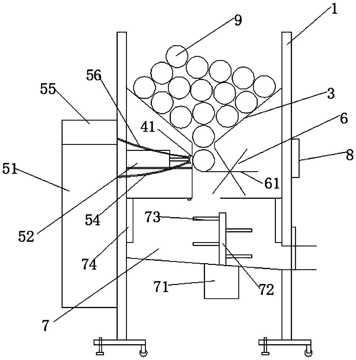
[0026] Embodiment 1: According to Figures 1 to 3 shown

[0027] A sphere coding and counting device includes: a box body 1, a support device 2, a bin body 3, a slideway 4, a spraying device 5, a sphere limit device 6, a drying chamber 7, a control display 8 and a sphere 9; A warehouse body 3 is arranged at the inner middle and upper end of the box body 1; a slideway 4 is arranged at the center of the bottom end of the warehouse body 3; a spraying device 5 is arranged on one side of the slideway 4; A sphere limiter 6 is set on one side; a drying chamber 7 is set at the middle and lower end of the box body 1; a support device 2 is respectively arranged at four corners of the bottom end of the box body 1, front, rear, left, and right; A control display 8 is arranged on the side of the box body 1, and the control display 8 is electrically connected to the device, and controls the operation of the device.

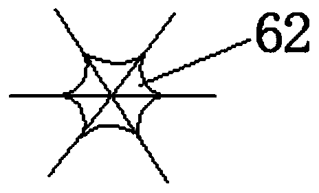
[0028] The sphere limiting device 6 includes a stirring limiting plate 6...

Embodiment 2

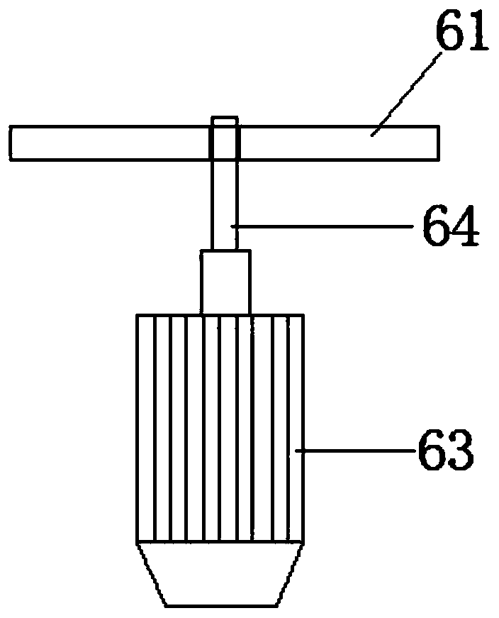
[0035] Embodiment 2: According to Figure 4 with5 shown

[0036] A sphere coding and counting device includes: a box body 1, a support device 2, a bin body 3, a slideway 4, a spraying device 5, a sphere limit device 6, a drying chamber 7, a control display 8 and a sphere 9; A warehouse body 3 is arranged at the inner middle and upper end of the box body 1; a slideway 4 is arranged at the center of the bottom end of the warehouse body 3; a spraying device 5 is arranged on one side of the slideway 4; A sphere limiter 6 is set on one side; a drying chamber 7 is set at the middle and lower end of the box body 1; a support device 2 is respectively arranged at four corners of the bottom end of the box body 1, front, rear, left, and right; A control display 8 is arranged on the side of the box body 1, and the control display 8 is electrically connected to the device, and controls the operation of the device.

[0037] Described sphere limiter 6 comprises transmission device 611, No....


PUM


Abstract

The invention discloses a sphere code spraying and counting device. The device comprises a box, a support device, a bin, a slide way, a spraying device, a sphere limiting device, a drying chamber, a control displayer and spheres; the bin is arranged at the middle upper end in the box; the slide way is arranged in the bottom end center of the bin; the spraying device is arranged on one side of theslide way; the sphere limiting device is arranged on the other side of the slide way; the drying chamber is arranged at the middle lower end of the box; support devices are arranged at front, back, left and right corners of the bottom end of the box; and the control displayer is arranged on the side surface of the box, is electrically connected with the device, and controls the device to operate.The device is reasonable in design, convenient to use, various in function, high in working efficiency and convenient to popularize.

Description

technical field [0001] The invention relates to the technical field of coding equipment, in particular to a ball coding and counting device. Background technique [0002] At present, most of the inkjet printers or inkjet printers with conveyor belts are used to spray the marking code on the sphere. Because the surface of the sphere is relatively smooth, it cannot be dried quickly after spraying the code, and the code is easy to be smeared. Make the mark unclear, it is difficult to guarantee the quality of the identification code on the sphere. Contents of the invention [0003] The object of the present invention is to provide a ball coding and counting device. [0004] To achieve the above object, the present invention adopts the following content: [0005] A sphere coding and counting device, comprising: a box body, a support device, a bin body, a slideway, a spraying device, a sphere limiter, a drying chamber, a control display and a sphere; The bin body; a slideway ...

Claims


Application Information

Patent Timeline
Patent Type & Authority Applications(China)
IPC IPC(8): B41J3/407B41J2/01B41J2/14B41J11/00B41J29/20B41J29/393
CPCB41J2/01B41J2/14B41J3/4073B41J11/002B41J29/20B41J29/393
Inventor 朱立飞
Owner 朱立飞
Why Eureka
Try Eureka