Environment-friendly flexible fireproof cable

A fire-proof cable and environmentally friendly technology, applied in the direction of lifting device, multi-axis trolley, trolley accessories, etc., can solve the problems that the cable is not easy to move, and the reel of the cable cannot be erected at will.

Active Publication Date: 2019-08-16
福建万嘉宝线缆有限公司
View PDF2 Cites 2 Cited by
  • Summary
  • Abstract
  • Description
  • Claims
  • Application Information

AI Technical Summary

Problems solved by technology

Traditional cables are not easy to move, and the reels of cables cannot be erected at will

Method used


Image

  • Environment-friendly flexible fireproof cable
  • Environment-friendly flexible fireproof cable
  • Environment-friendly flexible fireproof cable

Examples


specific Embodiment approach 1

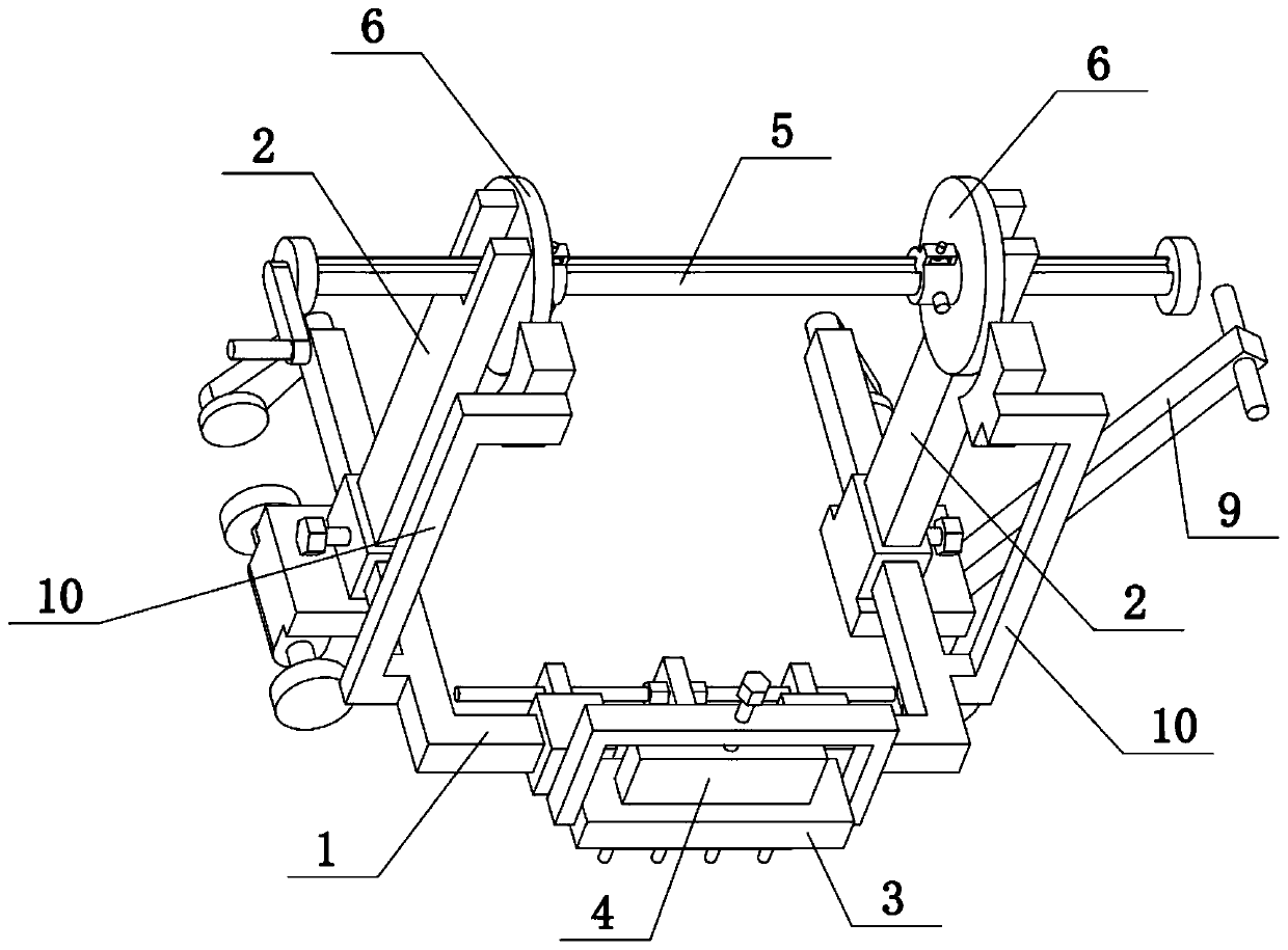
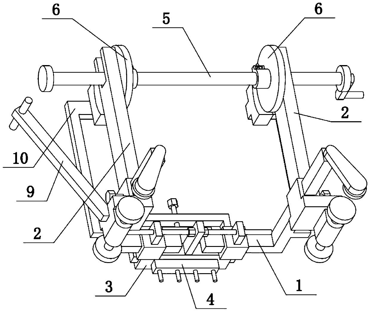
[0034] Combine below Figure 1-12 To illustrate this embodiment, the present invention relates to a cable, more specifically an environment-friendly flexible fireproof cable, which includes a bottom frame 1, a vertical frame 2, a middle connecting frame 3, a ground insert 4, a cable roll shaft 5, and a cable Limiter 6, cable 7, fireproof layer 8, handle 9 and fixer 10, the distance between two cable limiters 6 in the present invention can be adjusted, which is convenient for adjusting the two cable limiters according to the different specifications of cables 7 6; when the cable 7 needs to be moved, the cable shaft 5 and the two cable stoppers 6 can be fixed, and the runner 2-2 can be used to facilitate the movement of the cable 7; when the cable 7 needs to be used, the runner 2-2 can be moved. 2 lock, unfix the roll cable shaft 5 and the two cable stoppers 6, and erect the roll cable shaft 5 firmly.

[0035]There are two vertical frames 2 on the left and right, and the two ve...

specific Embodiment approach 2

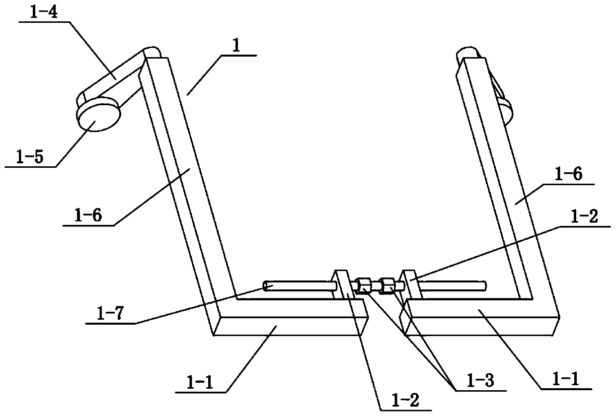
[0037] Combine below Figure 1-12 To illustrate this embodiment, the chassis 1 includes a square pole I1-1, a protruding piece 1-2, a hexagonal head 1-3, a pressing piece 1-4, a square pole II1-6 and a double-threaded screw 1-7 , there are two square pillars II1-6 left and right, the front ends of the two square pillars II1-6 are fixedly connected with square pillars I1-1, and the inner ends of the two square pillars I1-1 are fixedly connected with convex Sheet 1-2, the helical directions of the left and right ends of the double-threaded screw 1-7 are opposite, and the left and right ends of the double-threaded screw 1-7 cooperate with the two protruding pieces 1-2 through threads respectively, and the double-threaded screw 1-7 There are two hexagonal swivels 1-3 at the middle position, the two hexagonal swivels 1-3 are located between the two lugs 1-2, and the rear ends of the two square poles II1-6 are fixedly connected with pressing pieces 1-4. Rotating one of the hexagon...

specific Embodiment approach 3

[0039] Combine below Figure 1-12 To illustrate this embodiment, the vertical frame 2 includes a base plate 2-1, a runner 2-2, a wheel seat 2-3, a fastening screw 12-4, a fixing sleeve 12-5, a vertical bracket 2-6 and a rotating groove Mouth 2-7, the lower end of base plate 2-1 is fixedly connected with wheel seat 2-3, and the front and rear ends of wheel seat 2-3 are all rotatably connected with runner 2-2, and the upper end of base plate 2-1 is fixedly connected with The fixed sleeve I2-5, the fixed sleeve I2-5 is threadedly connected with the fastening screw I2-4, the upper end of the fixed sleeve I2-5 is fixedly connected with the vertical support 2-6, and the upper end of the vertical support 2-6 is provided with a rotation groove Port 2-7; the two vertical frames 2 are respectively slidably connected to the two square poles II1-6 through the fixing sleeves I2-5 on them, and the two fastening screws I2-4 are respectively supported on the two square poles II1 -6 on. The ...


PUM


Abstract

The invention relates to a cable, in particular to an environment-friendly flexible fireproof cable. The interval between two cable limiting parts can be adjusted, according to different specifications of the cable, the interval between the two cable limiting parts is adjusted, when the cable needs to be moved, a cable winding shaft and two cable limiting parts are fixed, a rotating wheel is usedfor facilitating cable moving, when the cable needs to be used, the rotating wheel is locked, fixing of the cable winding shaft and the two cable limiting parts is relieved, the cable winding shaft isstably erected, a left vertical frame and a right vertical frame are arranged, the two vertical frames are in sliding connection to the left end and the right end of a bottom frame, a middle connecting frame is arranged in the middle of the bottom frame, a ground inserting part is in sliding connection to the middle connecting frame, the left end and the right end of the cable winding shaft are rotatably connected to the upper ends of the two vertical frames, the left cable limiting part and the right cable limiting part are arranged, and the two cable limiting parts are in sliding connectionto the left end and the right end of the cable winding shaft correspondingly.

Description

technical field [0001] The invention relates to a cable, in particular to an environment-friendly flexible fireproof cable. Background technique [0002] Wire and cable are used to transmit electric energy, information and wire products to realize electromagnetic energy conversion. In the broad sense, wires and cables are also referred to as cables for short. In the narrow sense, cables refer to insulated cables, which can be defined as: a collection composed of the following parts; one or more insulated cores, and their respective possible coatings. Protective layer and outer sheath, the cable may also have additional uninsulated conductors. Traditional cables are not easy to move, and the reels of cables cannot be erected at will. Contents of the invention [0003] The invention provides an environment-friendly flexible fireproof cable, which has the beneficial effect that the distance between the two cable stoppers in the present invention can be adjusted, which is co...

Claims


Application Information

Patent Timeline
Patent Type & Authority Applications(China)
IPC IPC(8): B66F19/00B62B3/02B62B3/04B62B5/00B62B5/04
CPCB62B3/02B62B3/04B62B5/00B62B5/0457B62B2202/00B66F19/00
Inventor 郝同法
Owner 福建万嘉宝线缆有限公司
Why Eureka
Try Eureka