Middle corridor roof connecting structure

A technology for connecting structures and steel beams, used in building structures, buildings, etc., and can solve the problems of overlapping welds, poor strength and reliability, and low processing and installation efficiency.

Active Publication Date: 2019-08-16
CHINA CONSTR STEEL STRUCTURE CORP LTD
View PDF6 Cites 2 Cited by
  • Summary
  • Abstract
  • Description
  • Claims
  • Application Information

AI Technical Summary

Problems solved by technology

[0003] The roof of the central porch is directly welded at the joints of multiple steel beams and bifurcated columns, and the size and weight of each steel beam and bifurcated column make th

Method used


Image

  • Middle corridor roof connecting structure
  • Middle corridor roof connecting structure

Examples


Embodiment

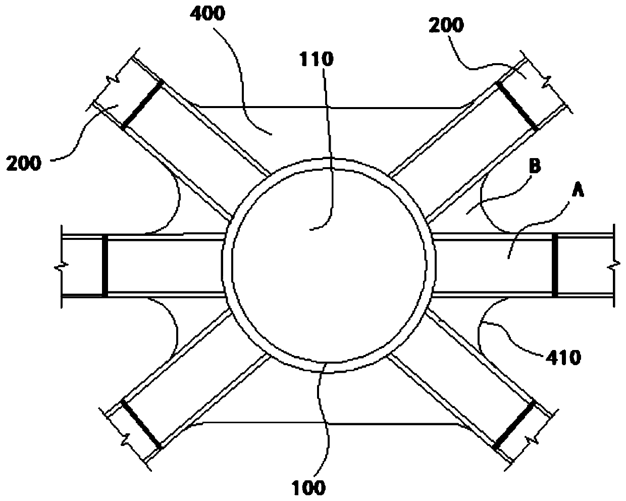
[0031] This embodiment provides a middle gallery roof connection structure.

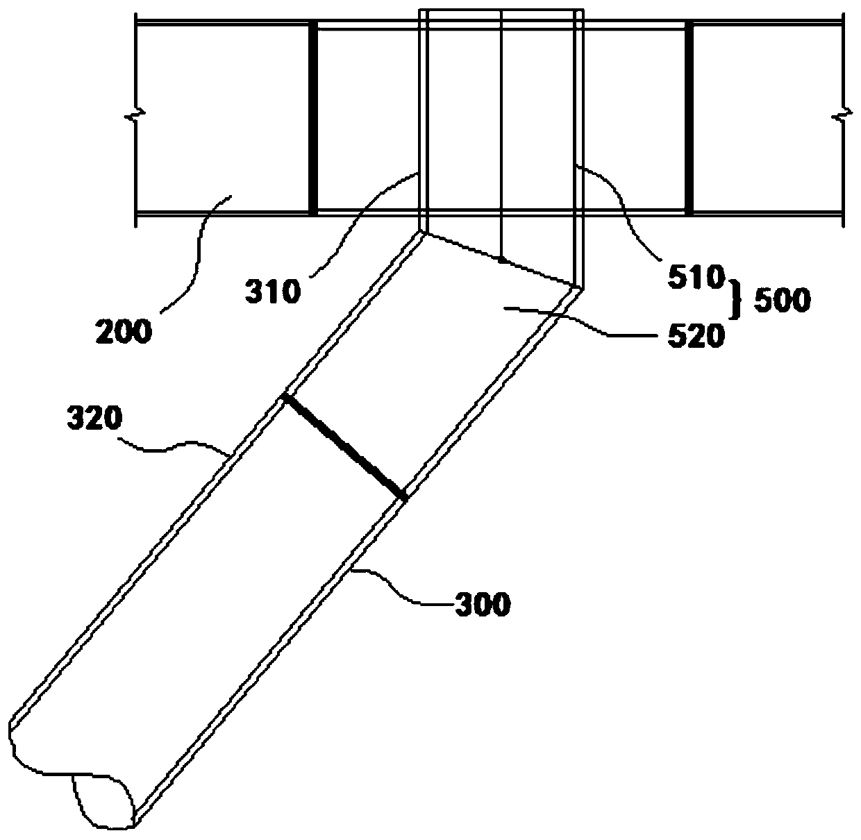
[0032] Please refer to Figure 1-2 , the corridor roof connection structure includes a central circular tube 100 , a roof steel beam 200 and a roof bifurcated column 300 .

[0033] Wherein, the intermediate round pipe 100 has a hollow installation channel 110 , which is mainly used as an intermediate medium for connecting the roof steel beam 200 and the roof bifurcated column 300 .

[0034] The roof steel girder 200 is welded to the peripheral wall of the intermediate circular pipe 100 , and the roof branch column 300 is welded in the installation channel 110 .

[0035] In this way, due to the setting of the intermediate circular pipe 100, the roof steel beam 200 and the roof bifurcated column 300 can be welded with the intermediate circular pipe 100 as the medium, and the roof steel beam 200 can be welded on the peripheral wall of the intermediate circular pipe 100, while The roof bifurcated colum...


PUM


Abstract

The invention discloses a middle corridor roof connecting structure, which comprises a middle round pipe, roof steel beams and roof fork columns. The middle round pipe is provided with a hollow mounting channel, the roof steel beams are welded to the circumferential wall of the middle round pipe, and the roof fork columns are welded into the mounting channel. During welding, the roof steel beams can be welded to the circumferential wall of the middle round pipe, the roof fork columns can be welded into the mounting channel of the middle round pipe, thus the phenomenon of weld joint coincidenceis greatly controlled, and the strength and reliability of a connecting joint are advantageously improved; and meanwhile, the difficulty of welding all the roof steel beams and all the roof fork columns to the middle round pipe correspondingly is greatly lowered, and the mounting and machining efficiency is advantageously improved.

Description

technical field [0001] The invention relates to the technical field of steel structures, in particular to a connecting structure for a middle gallery roof. Background technique [0002] Some large-scale steel structures, such as exhibition halls, need to build multiple independent exhibition halls first, and then need to set up a middle corridor between two adjacent exhibition halls. Gallery roof. [0003] The roof of the central porch is directly welded at the joints of multiple steel beams and bifurcated columns, and the size and weight of each steel beam and bifurcated column make the welding process complicated and difficult. The installation efficiency is low, and there is a large area of ​​welding seam overlap phenomenon, and the strength and reliability are not good. Contents of the invention [0004] This application aims to solve one of the technical problems in the related art at least to a certain extent. [0005] Therefore, according to an embodiment of the ...

Claims


Application Information

Patent Timeline
IPC IPC(8): E04B1/24E04B1/58
CPCE04B1/2403
Inventor 陆建新张爱明崔志勇隋小东胡保卫张弦苗凯张浩楠廖选茂
Owner CHINA CONSTR STEEL STRUCTURE CORP LTD
Why Eureka
Try Eureka