Roadway deformation monitoring device

A deformation monitoring and distance measuring device technology, which is applied in the direction of electromagnetic measuring devices, electric/magnetic solid deformation measurement, etc., can solve the problem that the end of the steel tape is rooted on the roof measuring point, which affects the validity of the measurement data, and the mine car damages the measuring device and other problems, to achieve the effect of not easy to shift, fixed firmly, and convenient to deform

Active Publication Date: 2019-08-16
NORTHEASTERN UNIV
View PDF8 Cites 4 Cited by
  • Summary
  • Abstract
  • Description
  • Claims
  • Application Information

AI Technical Summary

Problems solved by technology

On-site measurement methods generally use tower rulers or steel tapes to measure. During the measurement process, it is often difficult to find the floor measurement points because the roadway floor has been cleaned or leveled, or the floor measurement points have been displaced or damaged, which affects the measurement. In addition, when using a steel tape to measure, it is often not easy to root the end of the steel tape on the top plate measurement point, and the operation is more troublesome
[0005] In addition, a certain measuring device will be fixed on the roof on site to facilitate the use of each measurement. However, for coal mine roadways, most of them have the function of rail auxiliary transportation. During the transportation process, mine vehicles are prone to damage the measuring device. Phenomenon

Method used


Image

  • Roadway deformation monitoring device
  • Roadway deformation monitoring device
  • Roadway deformation monitoring device

Examples


Embodiment Construction

[0042] In order to better explain the present invention and facilitate understanding, the present invention will be described in detail below through specific embodiments in conjunction with the accompanying drawings.

[0043] An embodiment of the present invention provides a roadway deformation monitoring device, which is used to monitor the relative movement of the top and bottom of the roadway to determine whether the roadway is deformed.

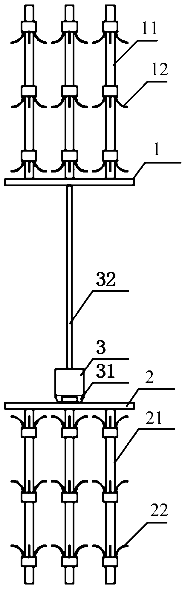
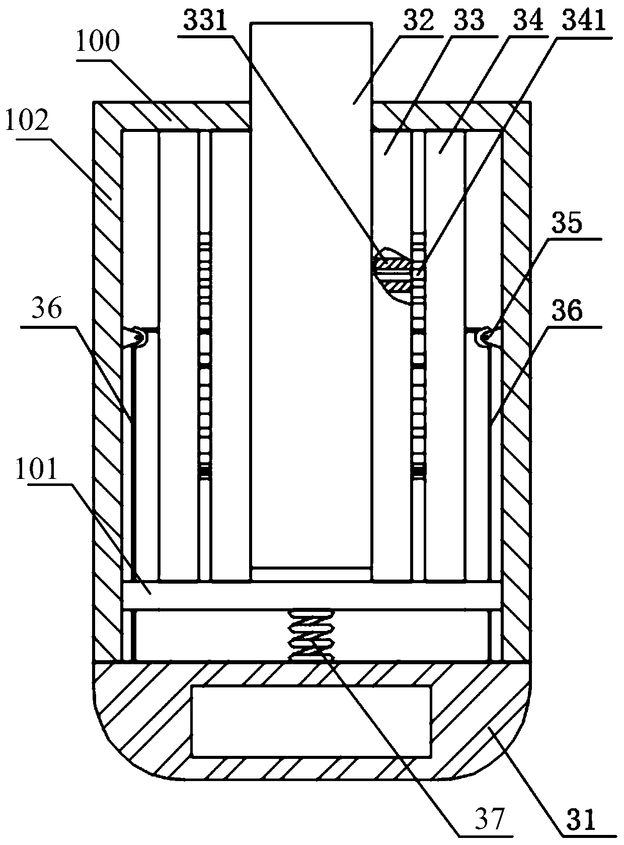
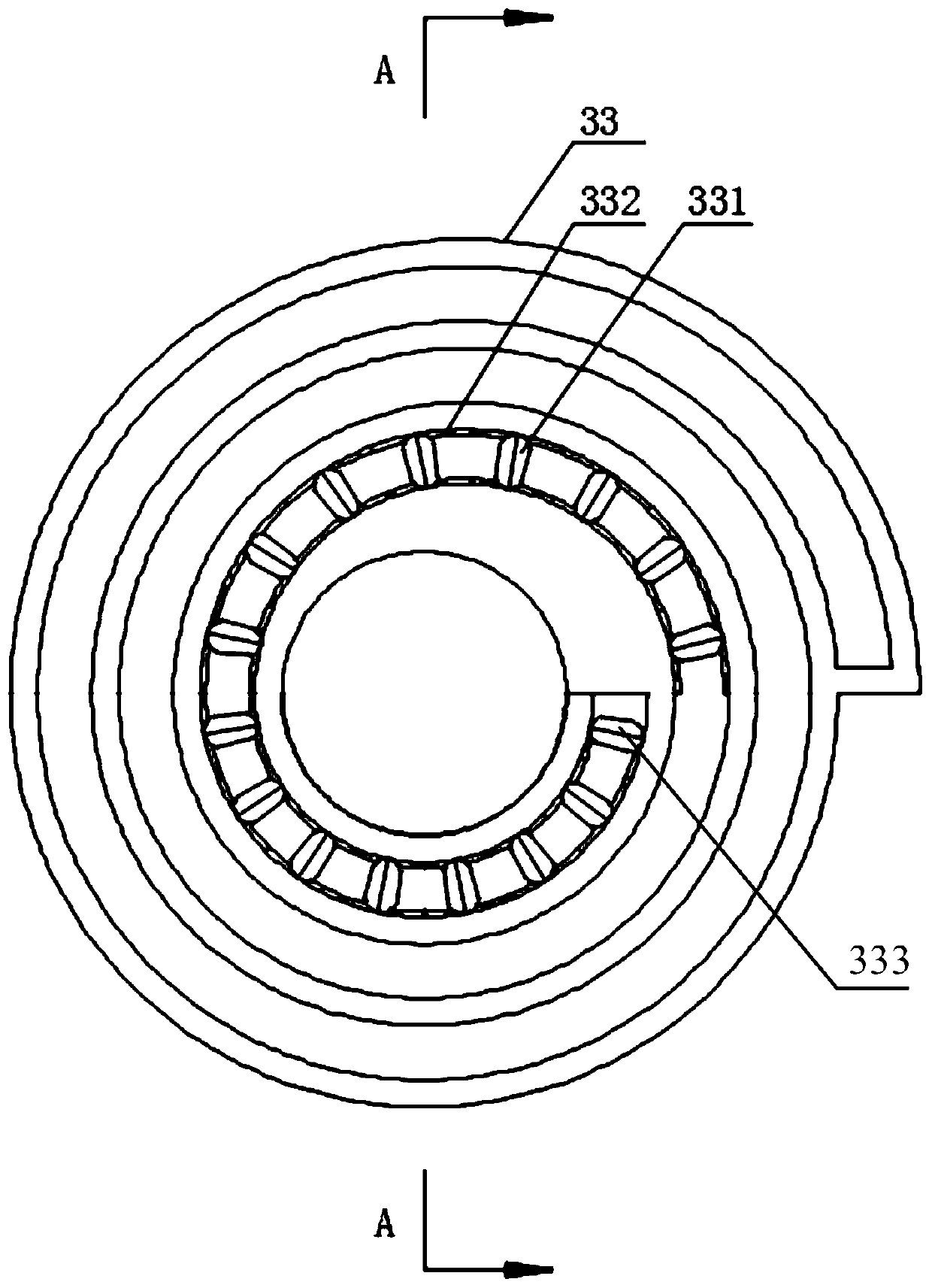
[0044] combine Figure 1-Figure 5 As shown, the roadway deformation monitoring device includes:

[0045] A top plate 1 and a bottom plate 2, the top plate 1 has a top measuring point, and the bottom plate 2 has a bottom measuring point;

[0046] Several first rooting rods 11, with a plurality of first rooting points 12 on the first rooting rod 11, one end of the first rooting rod 11 is fixedly connected to the top plate 1, and the top plate 1 passes through the several A first rooting bar 11 is fixed on the top of the roadway;

[0047...


PUM


Abstract

The invention relates to the technical field of engineering monitoring and discloses a roadway deformation monitoring device comprising a top plate and a bottom plate; the top plate and the bottom plate are respectively fixed at the top and the bottom of the roadway through a rooting rod with a rooting point, the roadway deformation monitoring device is firm in fixation and not easy to shift and damage, the effectiveness and accuracy of measured data are guaranteed, moreover, a distance measuring device is fixed at a top measuring point on the top plate through the free end of a graduated scale and is not easy to damage, during measurement, the measuring device is pulled to a bottom measuring point of the bottom plate through a pull ring, the distance between the top measuring point and the bottom measuring point is measured so as to monitor relative displacement of the top and the bottom of the roadway, whether the roadway is deformed or not can be accurately and effectively judged, and the operation is simple. In addition, the monitoring device is fixed on the top plate, after the measurement is finished, the pull ring is loosened, and the distance measuring device is reset to the top measuring point of the top plate through rollback of the graduated scale, such that the normal function of the roadway are not influenced, and whether the roadway is deformed or not can be conveniently judged through measurement.

Description

technical field [0001] The invention relates to the technical field of engineering monitoring, in particular to a roadway deformation monitoring device. Background technique [0002] The convergence of the roadway surrounding rock is the most basic data to confirm the stability of the surrounding rock, judge the support effect, guide the construction sequence, prevent the collapse of the vault, and ensure the construction quality and safety; the peripheral displacement is the change of the stress state of the roadway surrounding rock and the occurrence The most direct reflection of rheological deformation. By monitoring the dynamic changes of the surrounding rock and support structure at each construction stage, grasp the safety state of the structure during the construction process, judge the stability of the surrounding rock and the reliability of the support, and ensure construction safety and long-term stability of the structure. Therefore, for coal mines, all mining ro...

Claims


Application Information

Patent Timeline
Patent Type & Authority Applications(China)
IPC IPC(8): G01B7/24
CPCG01B7/24
Inventor 代连朋郭建霖董二虎
Owner NORTHEASTERN UNIV
Why Eureka
Try Eureka