
Novel wire precise clamping device

A clamping device and wire technology, applied in circuit/collector parts, electrical components, circuits, etc., can solve the problems of complexity, increase the labor intensity of operators, reduce operating time, facilitate laser engraving, and be convenient to use. Effect

Pending Publication Date: 2019-08-16
珠海市运泰利自动化设备有限公司
View PDF0 Cites 0 Cited by
  • Summary
  • Abstract
  • Description
  • Claims
  • Application Information

AI Technical Summary

Problems solved by technology

This method is more complicated and increases the labor intensity of the operator

Method used


Image

  • Novel wire precise clamping device
  • Novel wire precise clamping device
  • Novel wire precise clamping device

Examples


Embodiment Construction

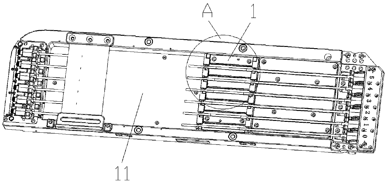
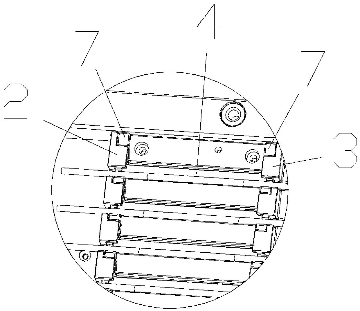
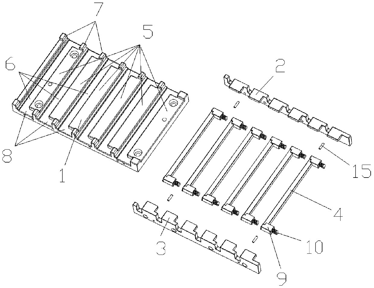
[0013] Such as Figure 1 to Figure 4 As shown, in this embodiment, the present invention includes a wire rod clamping base plate 1, a left baffle plate 2, a right baffle plate 3 and several movable blocks 4, and the upper end surface of the wire rod clamping base plate 1 is sequentially arranged from front to back There are several protrusions 5 equal in number to the movable clamping block 4, the first slots 6 are formed between the plurality of protrusions 5, and both sides of the plurality of protrusions 5 are provided with limiting protrusions 7. A second slot 8 is formed between the front and rear adjacent limit protrusions 7, and spring blocks 9 are arranged on both sides of the movable block 4, and the spring blocks 9 are arranged facing forward, so that A spring 10 is arranged on the spring block 9, the movable block 4 is fitted in the first slot 6, and the spring block 9 and the spring 10 are both arranged in the second slot. In 8, the left baffle 2 and the right baf...


PUM


Abstract

The invention discloses a novel wire precise clamping device and aims to provide the novel wire precise clamping device which has the advantages of convenience in use, compact structure and convenience in laser engraving and can be applied to wires of different wire diameters. The device comprises a wire clamping bottom plate, a left baffle plate, a right baffle plate and a plurality of movable clamping blocks. An upper-end surface of the wire clamping bottom plate is provided with a plurality of convex blocks with the same number of movable clamping blocks from front to back, first slots areformed between the several convex blocks, two side ends of the convex blocks are provided with limiting protrusions, second slots are formed between front and back adjacent limiting protrusions, two ends of the movable clamping blocks are provided with spring blocks which are arranged forward, the spring blocks are provided with springs in a matched way, the movable clamping blocks are set in thefirst slots in an adapted way, both the spring blocks and the springs are set in the second slots, and the left baffle and the right baffle plate are fixed to the left and right side ends of the wireclamping bottom plate in a matched way. The invention is applied to the technical field of wire clamping devices.

Description

technical field [0001] The invention relates to a novel wire precision clamping device. Background technique [0002] The data cable is used to connect mobile devices and computers to achieve data transmission or communication purposes. In layman's terms, it is a channel tool that connects computers and mobile devices to transmit files such as videos, ringtones, and pictures. At present, the method of clamping and positioning the data line is relatively traditional: for the data line with the need for wire engraving, the data line needs to be placed in the corresponding groove, and then manually covered with a cover, and then the lettering is carried out by laser. This kind of method is comparatively complicated, has increased the labor intensity of the operator. Contents of the invention [0003] The technical problem to be solved by the present invention is to overcome the deficiencies of the prior art, and provide a novel wire precision clamping device that is easy to ...

Claims


Application Information

Patent Timeline
Patent Type & Authority Applications(China)
IPC IPC(8): H01R43/28
CPCH01R43/28
Inventor 陈龙王珂
Owner 珠海市运泰利自动化设备有限公司
Learn More