Drive unit and method for controlling drive unit

A drive unit and drive motor technology, which is applied in the direction of motor control, control system, and mechanical energy control, etc., can solve the problems of large influence of tolerance, change of adjustment speed, and complicated application of drive unit.

Active Publication Date: 2019-08-16
DR ING H C F PORSCHE AG
View PDF14 Cites 0 Cited by
  • Summary
  • Abstract
  • Description
  • Claims
  • Application Information

AI Technical Summary

Problems solved by technology

[0004] Due to the fact that drive motors with drive units have different tolerances as drive units, the transmission ratios vary from drive unit to drive unit within the tolerance distribution, which complicates the application of such drive units
Especially under changing external conditions the influence on the tolerances is large, so the adjustment speed can vary greatly, which is not a desired situation

Method used


Image

  • Drive unit and method for controlling drive unit
  • Drive unit and method for controlling drive unit
  • Drive unit and method for controlling drive unit

Examples


Embodiment Construction

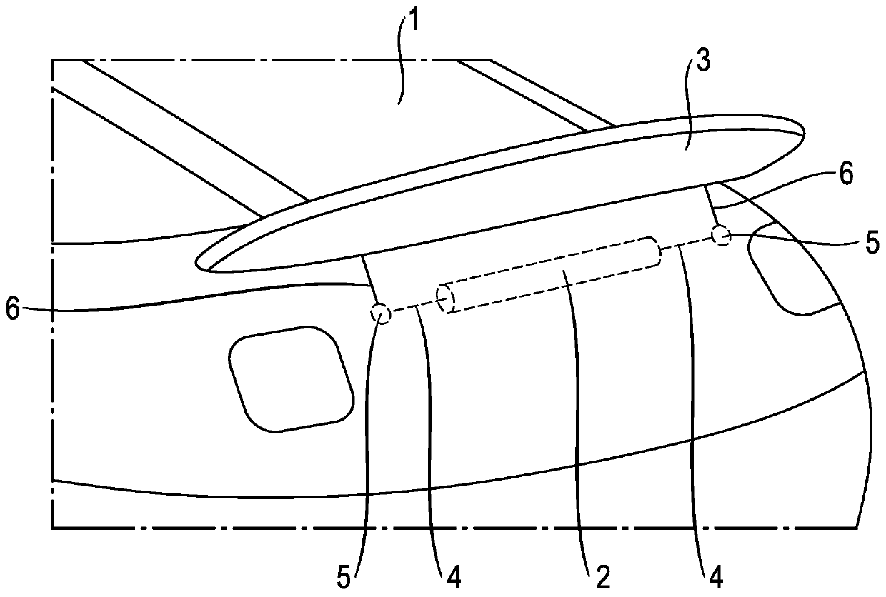
[0034] figure 1 Shown is a partial perspective view of a motor vehicle 1 with a drive unit 2 according to the invention for adjusting or actuating an air guiding element 3 , such as a rear spoiler. The air guide element here can also be other air guide elements, such as a front spoiler or the like.

[0035] The drive unit 2 for adjusting the air guide element 3 of the motor vehicle 1 has a drive motor with at least one transmission, which is connected to the drive motor as a combined unit and forms a drive motor-transmission unit, wherein The drive motor-gear unit has a rotatable shaft 4 on its two axial end regions, which can be driven via at least one gear to adjust the air-guiding element 3 .

[0036] In this case, the corresponding shaft 4 drives a mechanical device 5 , which actuates levers 6 arranged thereon on both sides of the air-guiding element in order to raise and lower the air-guiding element 3 .

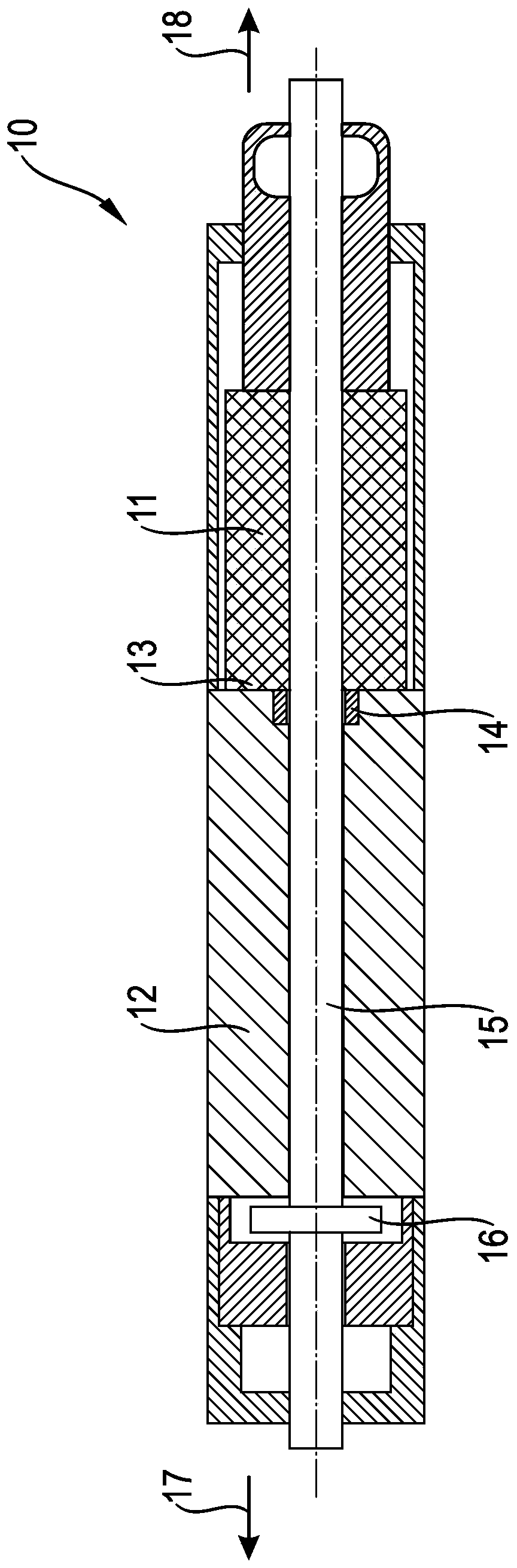
[0037] figure 2 Shown is an embodiment of a drive unit 10 acco...


PUM


Abstract

The invention relates to a drive unit (2, 10, 20, 51), in particular an air guide element (3) for a motor vehicle (1), comprising a drive motor (11, 21, 52, 129) having at least one transmission (12,22, 23, 53) which is connected to the drive motor (11, 21, 52, 129) as a combined unit and forms a drive motor-transmission mechanism unit. A control unit (54) for controlling the drive unit (2, 10, 20, 51) is arranged in the drive unit (2, 10, 20, 51), and a temperature sensor (60) for detecting the temperature of the drive unit (2, 10, 20, 51) is provided.

Description

technical field [0001] The invention relates to a drive unit and a method of controlling a drive unit, in particular for an air guide element of a motor vehicle. Background technique [0002] Known air guide elements on motor vehicles are spoiler elements which extend or adjust depending on the driving state or driving speed. For example, rear spoilers are known to retract at low vehicle speeds and extend after reaching a predetermined speed to increase downforce. [0003] DE 10 2013 100 518 A1 discloses an arrangement of a drive motor, which is coupled to a corresponding transmission mechanism connected thereto via two transmission shafts, wherein the power output shaft of the corresponding transmission mechanism is connected to the rear spoiler The adjustment kinematic mechanism is connected. [0004] Since drive motors with drive mechanisms have different tolerances as drive units, the transmission ratios between drive units vary within the range of the tolerance distri...

Claims


Application Information

Patent Timeline
Patent Type & Authority Applications(China)
IPC IPC(8): H02K11/25H02P29/68H02K7/116H02K11/30B62D35/00
CPCH02K11/25H02P29/68H02K7/116H02K11/30B62D35/00B62D35/007B62D37/02Y02T10/88H02P29/60
Inventor J·保尔C·保卢斯T·许贝纳
Owner DR ING H C F PORSCHE AG
Why Eureka
Try Eureka