Bumpy platform SAR three-dimensional motion error estimation method

A three-dimensional motion and error estimation technology, applied in the field of SAR imaging, can solve the problems such as the inability to meet the quality requirements of SAR imaging of bumpy platforms and the complex motion trajectory, to overcome the inability to compensate the space-variant phase error, improve the focusing effect, solve the calculation error and Effects of other disturbances

Active Publication Date: 2019-08-20
XIDIAN UNIV
View PDF3 Cites 12 Cited by
  • Summary
  • Abstract
  • Description
  • Claims
  • Application Information

AI Technical Summary

Benefits of technology

This technology helps improve the accuracy of 3D scanning by estimating errors caused during movement between different parts of an object being imaged due to factors like vibrations or imperfections such as uneven surfaces. It also includes filtering out weakly scattered areas from the raw data beforehand, making calculations more precise than previous methods. Overall, this innovation enhances the quality of 3 D images captured by current systems.

Problems solved by technology

The technical problem addressed in this patents relates to improving the performance of syntheic aperture radars due to their involuntional movements during operation. This movement causes degraded resolution when taking pictures at different angles. Current techniques like auto focus involve assuming constant values throughout time, which may result in significant ghost effects even after multiple exposures. There is also potential issue where incorrect calculations could lead to artifacts affecting the overall quality of the resulting picture.

Method used


Image

  • Bumpy platform SAR three-dimensional motion error estimation method
  • Bumpy platform SAR three-dimensional motion error estimation method
  • Bumpy platform SAR three-dimensional motion error estimation method

Examples


Embodiment Construction

[0029] The embodiments and effects of the present invention will be further described in detail below in conjunction with the accompanying drawings.

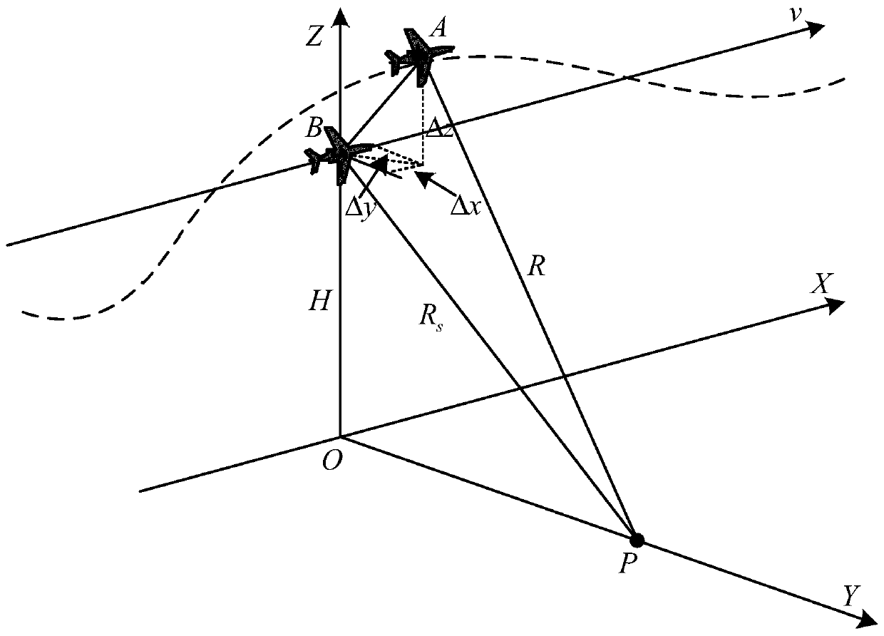
[0030] refer to figure 1 , is a schematic diagram of the imaging geometric model of the bumpy platform SAR; the bumpy platform SAR flies along the x direction (the azimuth direction of the radar) at a horizontal velocity v, where the solid line represents the ideal trajectory of the platform flight, the dotted line represents the actual trajectory of the platform flight, and point P is A target point in the scene. The flying height of the platform is H.

[0031] In an ideal situation, the platform will move in a straight line at a uniform speed along the track indicated by the solid line. Curved trajectory flight. Let point B be the slow time t in a certain direction m The ideal position of the radar antenna phase center (APC) when , its three-dimensional coordinates are, x 0 =[x 0 (t a ), y 0 (t a ),z 0 (t a )] T (i...


PUM


Abstract

The invention discloses a bumpy platform SAR three-dimensional motion error estimation method. A radar platform in the invention is a bumpy platform. For an imaging defocusing problem caused by a three-dimensional motion error of the bumpy platform, a plurality of strong scattering areas are screened according to an image contrast ratio in an original image without motion error compensation, a local phase error of each strong scattering area is estimated, and then, a total least square method is used to roughly estimate the three-dimensional motion error, and finally, the accurate three-dimensional motion error is obtained through Gaussian Newton iteration. In bumpy platform SAR imaging, by using the method of the invention, space variation compensation of the error can be realized, and then bumpy platform SAR imaging quality can be improved.

Description


Claims


Application Information

Patent Timeline
Owner XIDIAN UNIV
Why Eureka
Try Eureka