Multi-band-pass zero reflection filter

A filter and zero-reflection technology, which is applied to waveguide devices, circuits, electrical components, etc., can solve the problems of large circuit size, circuit structure or device performance limitations, and small absorption frequency range of reflected signals, so as to reduce the circuit size , Improve the absorption frequency range and reduce the number by half

Active Publication Date: 2019-08-20
HUAZHONG UNIV OF SCI & TECH +1
View PDF5 Cites 5 Cited by
  • Summary
  • Abstract
  • Description
  • Claims
  • Application Information

AI Technical Summary

Problems solved by technology

[0006] Aiming at the defects of the prior art, the purpose of the present invention is to provide a multi-pass band zero-reflection filter, aiming to solve the problem that the existing mult

Method used


Image

  • Multi-band-pass zero reflection filter
  • Multi-band-pass zero reflection filter
  • Multi-band-pass zero reflection filter

Examples


Embodiment Construction

[0035] In order to make the object, technical solution and advantages of the present invention clearer, the present invention will be further described in detail below in conjunction with the accompanying drawings and embodiments. It should be understood that the specific embodiments described here are only used to explain the present invention, not to limit the present invention.

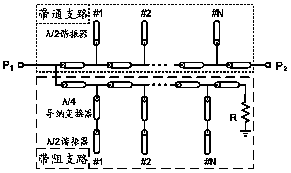
[0036] Such as Figure 4 As shown, the embodiment of the present invention provides a multi-pass band zero-reflection filter, including: a multi-mode resonator and a lossy absorption network;

[0037] The multimode resonator and the filter port P 1 The input feeder at the port P 2 The output feeder coupling at the place constitutes the bandpass branch of the filter;

[0038] Wherein, the bandpass branch is composed of a multimode resonator coupled to the input and output feedlines of the filter, or is formed by coupling a plurality of multimode resonators in series with the input and output feed...


PUM


Abstract

The invention discloses a multi-band-pass zero reflection filter which comprises a multi-mode resonator and lossy absorption networks. The multi-mode resonator is coupled to input and output feeders at ports of the filter to form a band-pass branch. A band stop branch of the filter is formed by the lossy absorption networks and an even mode equivalent circuit of the multi-mode resonator. Transmission poles of the band-pass branch are from even mode resonance points and odd mode resonance points of the multi-mode resonator. A half of transmission zero points of the band stop branch is from theeven mode resonance points of the multi-mode resonator. Resonance points of the lossy absorption networks are corresponding to the odd mode resonance points of the multi-mode resonator and are used asanother half of transmission zero points of the band stop branch. The transmission poles of the band-pass branch are corresponding to the transmission zero points of the band stop branch. According to the invention, the frequency absorption range of a reflected signal is improved by multiplexing the even mode resonance points of the multi-mode resonator, and the same time, the circuit size is reduced.

Description

technical field [0001] The invention belongs to the technical field of band-pass filters, and more specifically relates to a multi-pass band zero-reflection filter. Background technique [0002] The filter is an indispensable component in the RF front-end, which is used to realize the selection of the signal in the frequency domain. The working principle of traditional filters is to transmit passband signals and reflect stopband signals, which can be referred to as "stopband reflective filters". In the RF front-end chain, there are back and forth reflection signals between traditional filters and adjacent active modules, which will introduce additional intermodulation products to many active modules including amplifiers, frequency multipliers, mixers, etc. , Increase the gain fluctuation range, reduce the effective linear working range, reduce efficiency and other effects, so that the working performance of the active module in the link is significantly reduced. Therefore,...

Claims


Application Information

Patent Timeline
IPC IPC(8): H01P1/20
CPCH01P1/20
Inventor 毕晓君曹子兰
Owner HUAZHONG UNIV OF SCI & TECH
Why Eureka
Try Eureka